I’ve put together a video which details the problems I’m having, what I’ve done to try and correct them and links to the resources I’ve used (in the video description).
Laserbot - mLaser software issues
Xen0phobe
#42
I cut another rectangle with the following gcode:
M4 P0
G0 F2000.0
G0 X0 Y0
M4 P240
G1 F400.0
G1 X190 Y0
G1 X190 Y230
G1 X0 Y230
G1 X0 Y0
M4 P0
G0 F2000.0
G0 X0 Y0
As you can see from the code, the rectangle should measure 190 x 230 mm. When etched with Laserbot, however, the resultant rectangle measures 194.0 x 234.5 mm.
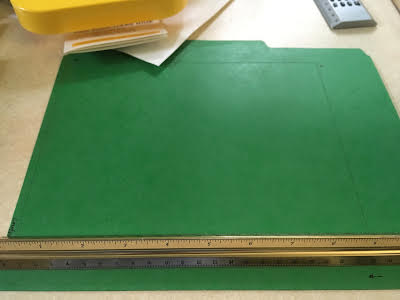
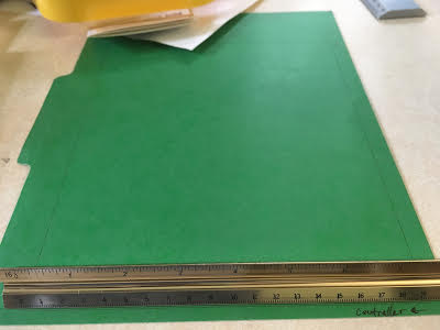
Also, the rectangle is skewed so that the lines that makeup the long and short sides (Y and X, respectively) are not perpendicular. The long edge of the rectangle is off from being perpendicular to the short edge by 1.5 mm.
Finally, I have included a picture of my X-axis so you can see that it sits flush against the U1 brackets.
Xen0phobe
#44
Default settings. That being said, I wrote a program which can be found in the video description that removes extraneous gcode commands that mLaser has trouble with. After gcodetools, I process the code with this program.
gmanx
#45
To accurately scale an SVG you need to understand mLaser software is using the DOCUMENT size not the actual drawing. I can output exactly the dimensions I want now once I figured this. Also double clicking on the drawing in mLaser brings up the size form but once you do this move the image as it will be off x0,y0.
To make this easier for me to figure out I now do square documents in Inkscape then - your drawing dims inside the page is generally ignored & scaled to the dociment size. It’ works every time now - let me know if I need to explain it better though!!
gmanx
#46
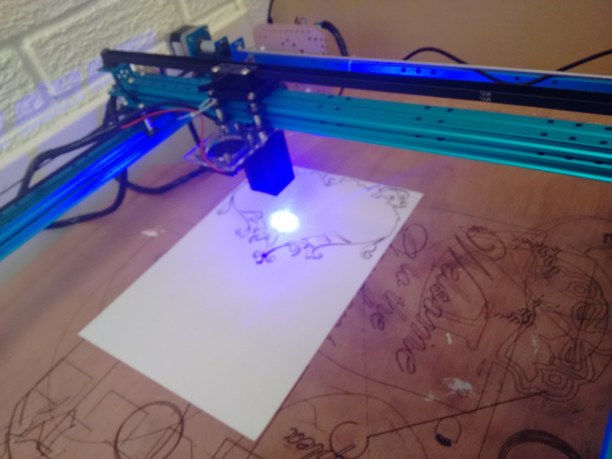
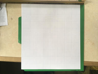
Ornamental lace design cutting on A4 paper - set to 200mm wide & it is 200mm wide exactly. I have done quite alot of accurate intricate cutting with good precision.
document size was actually 210x210mm but I scaled it in mLaser to 200x200mm
lace 210mm.zip (25.6 KB)
Xen0phobe
#47
LASERBOT PRECISION EXPERIMENT
The purpose of this experiment is to standardize what each of us is cutting - and the method in which we cut - so that we may more easily compare results. I have intentionally tried to keep the cutting pattern as simple as possible, so as to narrow the range of possible causes for errors. In the same vein, I have opted to use mLaser’s Gcode Mode, instead of its GUI, so as to remove faulty drawing interpretation as a possible problem.
MATERIALS
- Something to cut or etch that is at least 190 x 230 mm (A piece of paper will work swimmingly: US Letter - 8.5 x 11").
- A ruler at least 230 mm in length.
- A digital camera so you can post a picture of your results.
PROCEDURE
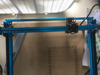
- Place the thing you want to cut under the laser's Home location (X 0, Y 0). Unless you have fiddled with the settings and changed the Home location, this will be in the corner of the cutting area right next to the circuit board - e.g. where there laser ends up when you run the Machine Self-test. If you are using a piece of paper, make sure it is oriented so the short edge is facing the circuit board - i.e. portrait instead of landscape. Also, make sure you have something under the paper, as the laser will burn through and etch whatever's underneath.
- Paste the following gcode in a text editor and save it as test_rectangle.gcode. M4 P0 G0 F2000.0 G0 X0 Y0 M4 P240 G1 F400.0 G1 X190 Y0 G1 X190 Y230 G1 X0 Y230 G1 X0 Y0 M4 P0 G0 F2000.0 G0 X0 Y0
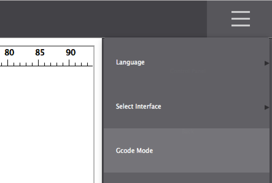
- Open mLaser and put the program in Gcode Mode. To do this, click on the three, grey horizontal bars in the upper-right corner of the Interface and then select Gcode Mode from the dropdown. This will open a new window entitled GcodeControl.
- Click Load and then select the test_rectangle.gcode file you made in Step 2.
- Click Finish and Laserbot should start cutting the rectangle.
- Once Laserbot is done, measure the rectangle with your ruler. It should be exactly 190 x 230 mm.
A little info on gcode: Gcode is a standardized machine language used by many industrial machines around the World. For instance, when Laserbot is given the command G1 X190 Y0, it is being told to move its tool head (the laser) EXACTLY 190.00 mm to the right (it actually moves to the left because Laserbot flips everything, but that’s another issue outside the scope of this post). Regardless, the point is that whatever the machine - whether it be a router or a 3D printer - if it is using the same basic, metric settings, there should be no mystery about the results it should produce.
A neat tool for previewing gcode files can be found here: https://nraynaud.github.io/webgcode/. Try pasting the gcode from this Experiment to see what the expected results should look like.
- Post pictures of your results with the ruler visible and let me know how close you were to the expected 190 x 230 mm rectangle. Please round your measurements to the nearest 0.1 mm, as the website for Laserbot states, “High-precision: Up to 0.1mm, carefully engraves every details”. For example, my rectangle measured 194.0 x 234.5 mm and was therefore imprecise by an average of 4.25 mm.


rene_bohne
#48
my results with latest firmware, mLaser 2.4 Windows 10: 194.0 x 234
I think that we have to:
- tune some parameters in the firmware
- create a custom visicut.org driver based on the default grbl driver: https://github.com/t-oster/LibLaserCut/blob/develop/src/com/t_oster/liblasercut/drivers/Grbl.java
gmanx
#49
Ran your G-code. Results best I could measure with a normal ruler:
x 193.3 (3.3mm too big or 1.73% error) y 233.6 (3.6mm to big or 1.56% error)
I then created an SVG document 230x190mm & got pretty much the same.
Following on I scaled the SVG 75%, 50% & 25%:
75% Should be 172.5x142.5 result: 175x145m (1.78%/1.47%)
50% Should be 115x95mm result 116.5 x 96.5mm
25% Should be 57.5x47.5mm Result 58x48.5mm (0.88%, 1.05%)
My measuring is not that accurate but the error is fairly proportionate so much more noticable on larger engravings.
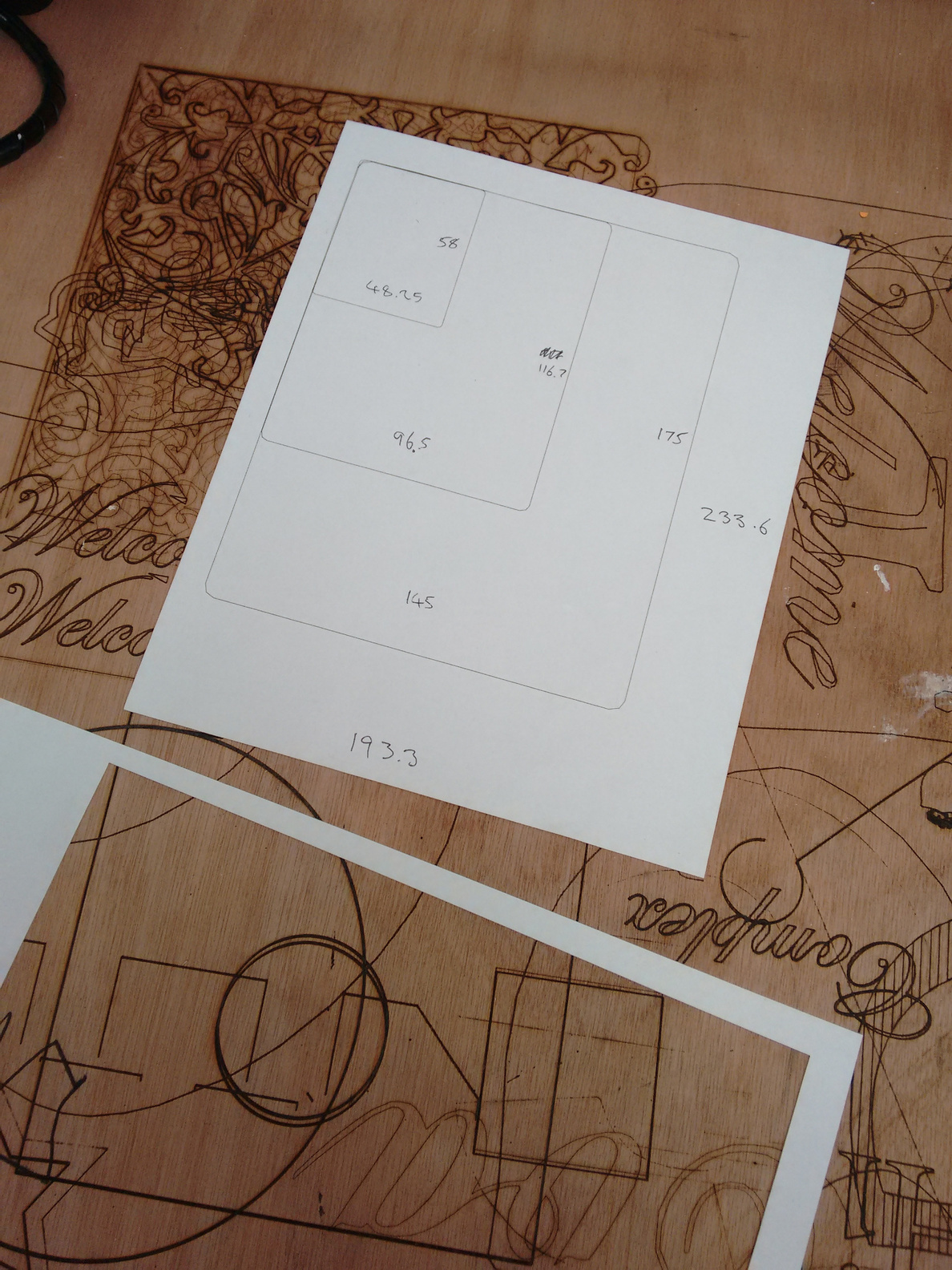
(n.b. the attached SVG (file: 230x190mm.zip) has rounded corners as the intrepreter does not like plot points in the origin or extreme x,y but that’s a whole different issue! For the work I’m doing I don’t cut squares much!)
gmanx
#50
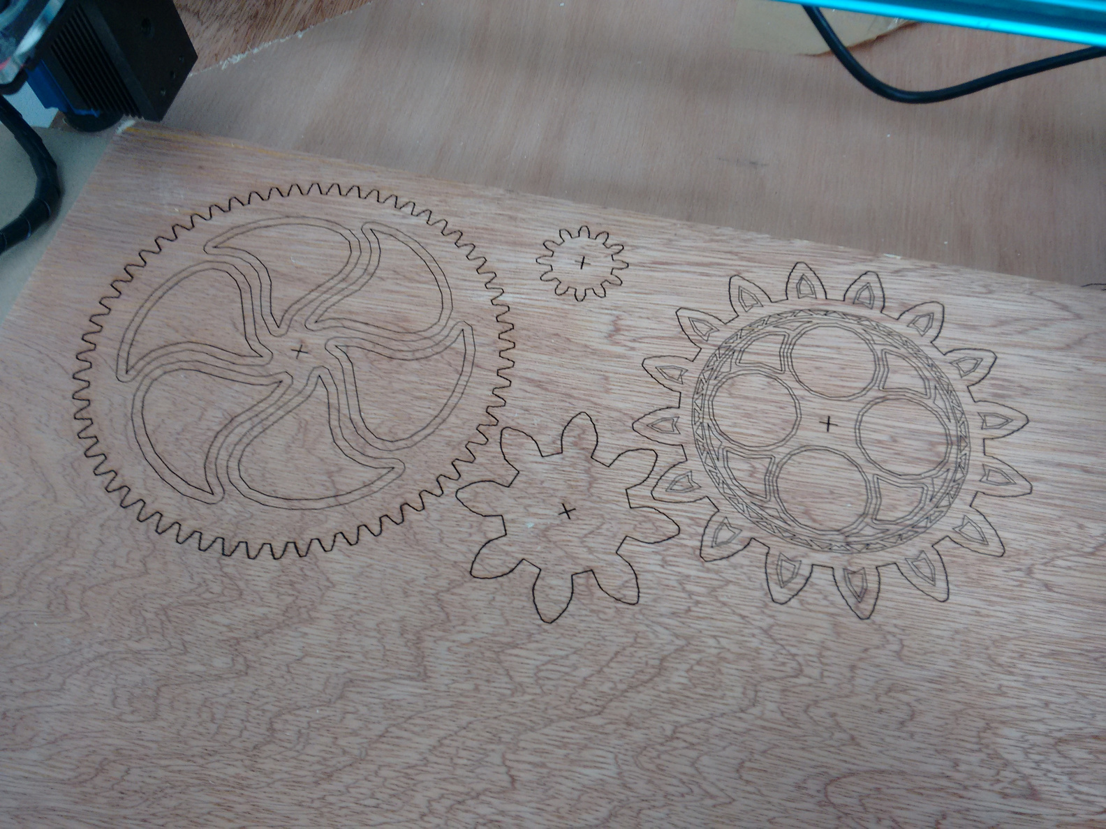
This is a cut I needed accuracy. 4 gears - left one should be 150mm diameter. First test was 152mm. (1.33% too big)
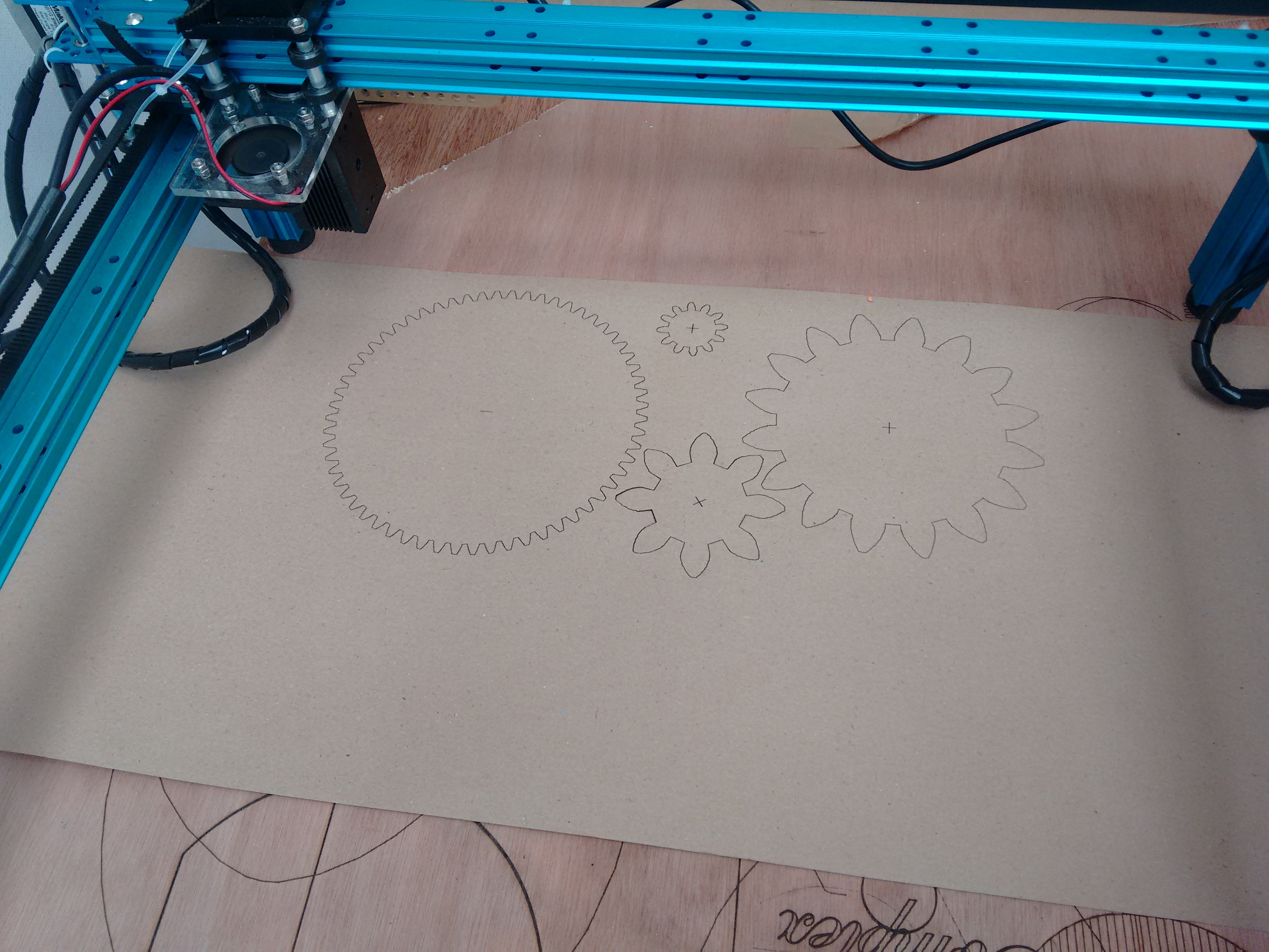
I had to do 2 further test cuts to get an accurate 150mm diameter. i ended up scaling drawing down 1.863%.
Gears were generated in www.geargenerator.com exported as SVG to layout in Inkscape.
This final photo shows the finished etch on plywood. I actually did the basic outline first & ran the laser over it several times to check if it was consistant. Then I did an revised SVG with the detailed bits over the top & it cut exactly the same several times.
Think the problem is a scaling issue rather than machine accuracy.
Xen0phobe
#51
I’m pretty sure it’s not just a scale issue.
I wrote a javascript program that you can find here (https://github.com/Xen0phobe/Gcode-Corrector-for-Laserbot/blob/master/index.html) that will scale gcode coordinates by whatever percentage you want. Even after using the program, I could not get precise results.
I also tried different scaling/ transform methods in Photoshop and Illustrator, thinking that altering the origin of the scale/ transform might fix things. It did not.
Please keep trying. Hopefully you can find a solution and share it with the rest of us. As for me, I’m trying to get my money back.
gmanx
#52
I am hoping they will do a software release to fix all the issues. Basically we have a stripped down rep-rap Mendel with a Laser module with Marlin code so there will be a solution. Just wish we didn’t need to try to fix it
Have many years hacking/coding & working on various 5 axis CNC workstations & CNC saws so know there are many ways to approach this. I will try to write an easy to understand blog post on how to get consistent results.
What worries me is the lack of activity in github mLaser page.
gmanx
#53
Just a quick note on mLaser Gcode. It does support curves:
M4 P0
G0 F2000.0
G0 X0 Y0
G0 X100 Y100
G1 F400.0
M4 P220
G2 X100 Y125 I12.5 J12.5
G1 X150 Y125
G2 X150 Y100 I-12.5 J-12.5
G1 X100 Y100
M4 P0
G0 F2000.0
G0 X0 Y0
The scale may be 1-2% off but I’m looking into that.
Another example I have managed to find a different extension for Inkscape to export clean gcode. Will post details over the weekend. Example qith 2 curves:
G0 X18.80 Y66.95
G1F500
M4 P200
G02 X47.10 Y68.17 I14.93 J-17.75
G03 X78.64 Y66.95 I16.70 J23.70
G1 X78.64 Y27.11
G1 X18.80 Y27.11
G1 X18.80 Y66.95
M4 P0
G0 X0 Y0
svogl
#54
… let me add a few notes: MakeBlock did publish their code on their github account under MLaser.
The firmware source is included, it is based on a rather old Marlin fork; besides some code for the robot arm, the major difference is to send back ‘oMG’ instead of ‘ok’.
I forked a more recent Marlin version and added support for the LaserBot, and it does print to the millimeter. If you want to have a look, its on github as well: LaserBot Marlin .
Besides, I patched MLaser to work with standard firmwares, accepting both oMG answer strings from their original firmware and the standard ‘ok’ string : MLaser patched.
As already written above, I want low-level control over the laser, so I skipped MLaser altogether but I’m using pronsole / pronterface for now.
Simon
Xen0phobe
#55
With your modified firmware is your Laserbot able to cut with better precision?
How does it fare on the Rectangle Test? Laserbot - mLaser software issues
I’m about ready to return mine, but if different firmware solves the precision problems, I’ll keep it. 
svogl
#56
Hmm, my game might not be yours… I am into computer science, so having a decent GUI is not an issue for me, I can live with command-line tools (short version: inkscape+gcodetools extension; pronterface / pronsole for printing ; I am looking into VisiCut, but lack time…).
When I print - say - a 100x100mm square I do get that to sub-mm precision.
My personal problem is laser startup control: When starting a line, the laser does not turn on for the first few mm, quite uncontrollable… I am looking for a new laser module right now, the rest of the mechanics and firmware is quite fine - I just dumped MLaser.
As for MLaser - I forked it and extended it to accept ok messages from standard firmware.
Xen0phobe
#57
Yeah, I don’t care about a GUI either. If you look at Rectangle Test I linked you to, it’s just Gcode.
If you could humor me and try the example, that would be really helpful. I’ve been going back-and-forth with Makeblock Tech Support and even THEY couldn’t get the rectangle to be the right size (their rectangle was 191.06 x 232 mm). If you’re able to get sub-mm precision, I will not only be amazed, but incredibly grateful as you will have saved me the hassle of returning the product.
svogl
#58
Well then let me amuse you: I printed your gcode and it turns out to be exact to ~0.1 mm or so; I did only a quick read with a standard ruler; the target is a little burnt - the neon pink paper absorbed the UV quite well it seems:
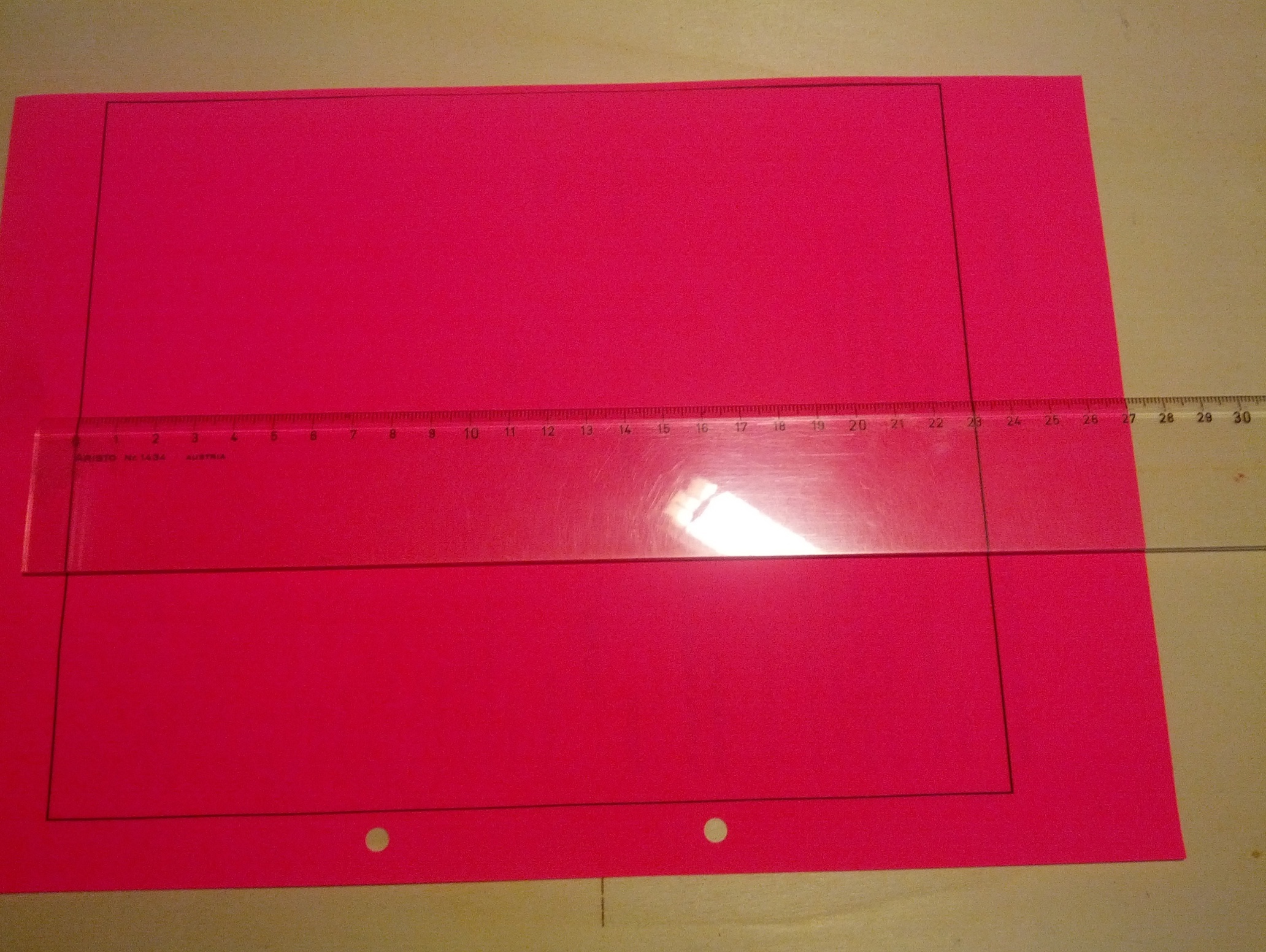
As said, I have laser control issues which are not less troublesome… (tech support promised to provide a solution weeks ago, no answer still - judge on your own)
Simon

