Laserbot - mLaser software issues


#21

@tec_support
Is there any progress on this?

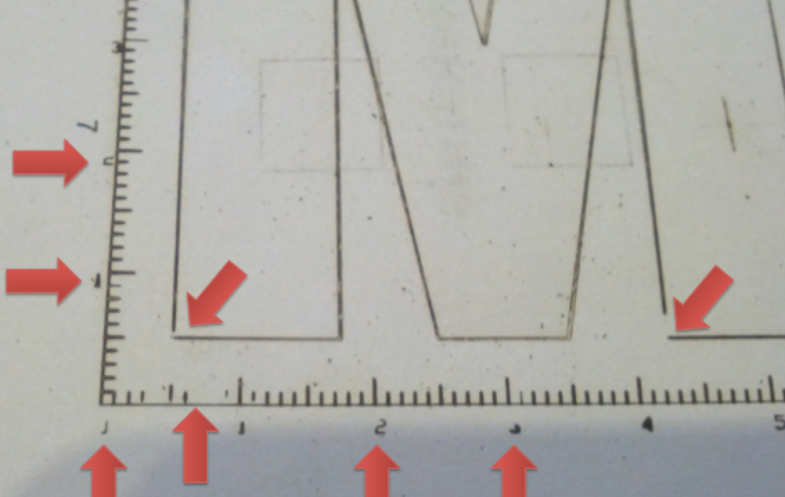
Laser startup is still totally erratic, as you can see from the following test-cut; I indicated cutting direction and sequence of the squares:

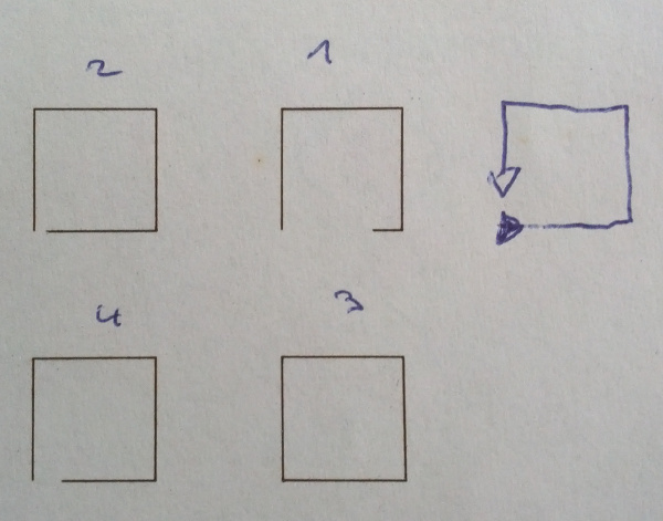
I think that the laser module is broken, would you please help us to get this working or confirm that it just works this way and not any better?

Btw, in order to rule out other possible causes I tried to

  • tried to keep the laser turned on when moving between squares (with pwm rates from 20-120)
  • Use a higher-rated power supply
  • added an 470uF/16V Elko parallel to the dust fan (there is no stabilizing capacitor near the power supply, only at the motor drivers)
  • changed to the second PWM output (ruling out a faulty Mosfet)

None of the changes could resolve the issue.

If the LaserBot should be able to print full rectangles, can I exchange the laser module?

P.S. here’s the GCode:

G21 (All units in mm)
G00 X30.098856 Y30.098852 S0
M4 P210(Subpath start)
G01 X39.901143 Y30.098852 F800.000000 S255
G01 X39.901143 Y39.901138 S255
G01 X30.098856 Y39.901138 S255
G01 X30.098856 Y30.098852 S255
(Subpath end)
M4 P00

G00 X10.098858 Y30.098852 S0
M4 P210(Subpath start)
G01 X19.901145 Y30.098852 F800.000000 S255
G01 X19.901145 Y39.901138 S255
G01 X10.098858 Y39.901138 S255
G01 X10.098858 Y30.098852 S255
(Subpath end)
M4 P00

G00 X10.098858 Y10.098849 S0
M4 P210(Subpath start)
G01 X19.901145 Y10.098849 F800.000000 S255
G01 X19.901145 Y19.901136 S255
G01 X10.098858 Y19.901136 S255
G01 X10.098858 Y10.098849 S255
(Subpath end)
M4 P00

G00 X30.098856 Y10.098849 S0
M4 P210(Subpath start)
G01 X39.901143 Y10.098849 F800.000000 S255
G01 X39.901143 Y19.901136 S255
G01 X30.098856 Y19.901136 S255
G01 X30.098856 Y10.098849 S255
(Subpath end)
M4 P00
M84

#22

Hi svogl,

The new version mLaser 2.4 is published. It has been updated but may not fix the problem totally. Anyway, you can try it first.
Our engineers are still working on it to solve the issues.


#23

Thanks for the update @tec_support ; mLaser for MacOS is still 2.3 on the web-page - will there be an update?

Nevertheless, I have tried the mLaser code on github which gave me the same errors. N.B.: I get printing artifacts when printing out the test-gcode (ruler+M) – the first parts of the ruler is missing.


#24

@tec_support - as the laser module is obviously broken, how can I get a replacement or instructions to fix the driver electronics?
Thanks


#25

Hi svogl,

It looks like you use Windows 10.
Anyway, we will consult our engineer about the development plan for mLaser software. Will let you know after confirmed it.
For the issue that the squares engraved are not closed, actually, this should be issue on mLaser software instead of the Laser module. Please check if there is any improvement on this issue with mLaser 2.4.


#26

@tec_support: I am using Mac OSX Sierra 10.12.4

I have tried different patterns, speeds, settings and different firmwares: The laser fails to start up correctly under any tested condition.
I do know a deal about software and electronics… :wink:

Could you please forward this problem to the electronics team? I can test a few things here if needed.


#27

Hi svogl,

Yes, this has been confirmed with our engineer, it is the firmware issue on mLaser software.
For newer version mLaser on Mac,time is still in the arrangement.


#28

Hi @tec_support,
I borrowed a Windows 10 laptop, installed mLaser 2.4, updated the firmware (twice) and printed the test pattern:


The result is no way better, so I suggest that my laser module is broken.
Exchange please?


#29

Hi Svogl,

It is true this issue has’t be totally solved on this version software since our engineers are still searching for a perfect way to solve it.
We have provided feedback of this case to both our software and hardware engineers teams, they are pretty sure this is a software issue. If it is really issue on the Laser, we won’t insist on this, hope you can understand.
Anyway, we are sorry for the issue which is still unsolved, our engineers are still working hard on it, please kindly wait for our further updates. Thanks!


#30

If it helps: At least in my case it seems connected to the spinning-up of the cooling fan. When it starts from zero or low frequency, the gaps are bigger than for shorter off-intervals.

Edit: I tried to constantly power the cooling fan from a secondary cable – results are considerably better (shorter outages), but it did not resolve it fully.


#31

I have similar issues to you. I think the issue is mainly software related. Engrave mode from image seems fine but SVG files are not. It appears to be something to do with the furthest corner points being missed. How do Text (not SVG imported) fonts come out for you in CUT mode? Non SVG Text doesn’t create the same issues for me and works well which suggests a software issue.


#32

@tec_support I have been doing further tests with SVG. The scale issue appears to be to do with document size. I noticed your 40mm square test SVG is 93.75mm in Inkscape.

I just cut a shield design which was smaller than the document page size. The software ignored the shield size cutting it to the max blue dotted page size (in mLaser 2.4) I think this means I can cut things the size I want using this temporary hack - cut will be document size not drawing.

Please can you adjust the scale to 1:1 mm?


#33

@tec_support Also can you add numeric scaling so accurate scaling can be achieved.


#34

Hi gmanx,

According to your description, it looks like you have the same issue with the krouviere in the same post here.
This issue happens only on svg file duo to that the mLaser software has yet compatible with all the svg file properly. We have provided feedback of this case to our engineers, we are still waiting for the improving. Thanks for your feedback and will inform here when there is update.


#35

@tec_support @krouviere I have managed to hack accurate scaling using SVG. Using Inkscape & mLaser 2.4.

(1) First save your drawing in Inkscape in a square document size. Make sure your drawing is filling most of the page size.
(2) Open SVG into mLaser. Ignore the scale ruler in mLaser - the SVG WILL BE THE SIZE OF THE BLUE DOTTED LINE in either height or width. Double click on the svg to open numeric input & set the correct height or width you wan t(n.b. this depends on your drawing so do step 4 to test - only use preview engraving area to set top/left edges)
(4) Set laser intensity to 10%. Start your engraving to check ok. It might be your drawing needs the height setting rather than the width to get the right scale.
(5) Set laser to your preferred setting (i use 90/100%) Cut your design.

This is a temporary hack while waiting for software update. Another thing worth noting is mLaser doesn’t like points in the top/left or bottom/right corners so design with that in mind - it probably will ignore them.

I hope this makes sense - I’m now able to cut at exactly the size I want accurately.


#36

Thank you for posting this as a workaround. Will give it a shot next time I need to use it.


#37

Hi, as another two weeks passed, and update and or timeline for a solution would be a great help.


#38

Simon,

I recently put the Laserbot together and I’ve encountered the same problems. Even when using gcodetools, Laserbot seems to ignore units of measurement and increase the scale of whatever gcode it’s fed. I looked at the file for the Makeblock test pattern (firsttest.gcode) and the difference between each millimeter dash on the rulers seems to be a consistent 0.9904 mm, when it - of course - should be 1 mm. What’s really strange is the incorrect coordinates in the file produce accurate results when the test pattern is actually burned.

I wrote some javascript code to parse through the gcode file and increase / decrease each coordinate by a set percentage. It’s still not quite working.

Anyways, I was wondering if you’ve made any progress, or if I should return this contraption? I’ve wasted far too much time on something that should have worked from the start. :unamused:

Laserbot engineers, if you could please tell me what program you used to create the firsttest.gcode file, and how you scaled it, that would be a start. If I could just get the machine to etch things the right size that would probably be enough to warrant me keeping it.

I’m simply trying to cut-out some circular stickers. :tired_face:


#39

Hi @Xen0phobe ,

Honestly, I have given up on this device - the laser startup problems make it unusable for real work (cutting/engraving many smaller pieces). This looks like a design flaw in the laser drive electronics that the engineers refuse to comment/fix.

Might be using it for some fun stuff, but it’s a toy, nothing more.

the 0.9904 though look like a scaling error coming from the timing belt tooth distances (my suspicion is: 0.9904 * 2.032 mm / 2.000 mm = ~1.006 ).
Good luck
Simon


#40

Hi Xen0phobe,

Sorry for the trouble caused.So the measurement for the test file M prints okay on your side. But the measurement is incorrect when print your own file.
Could you please kindly send your file which you want to draw. The firsttest.gcode file is created by the mLaser software too when it was imported to the software.

As for the issues on the mLaser software, we will urge the process again.