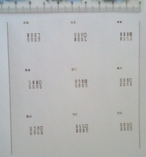
I received a Laserbot the last days and it assembled fine - great video instructions! The first test was the big M pattern with the scales - it came out fine and the scales were perfectly right - great!
The mLaser software looked nice (just wondered why I would need a password?), but here the troubles start: I intend to do some “serious” cutting (pcb stencils etc.), so I tried to import a Kicad print (via print to PDF/Inkscape detour), printed on paper an got
- the original PCB is 99x99mm --> HOW DO I SCALE this to get correct results? Inkscape exports with full page as the viewport, computing a scale vector is plain impossible (tried different files/settings)?
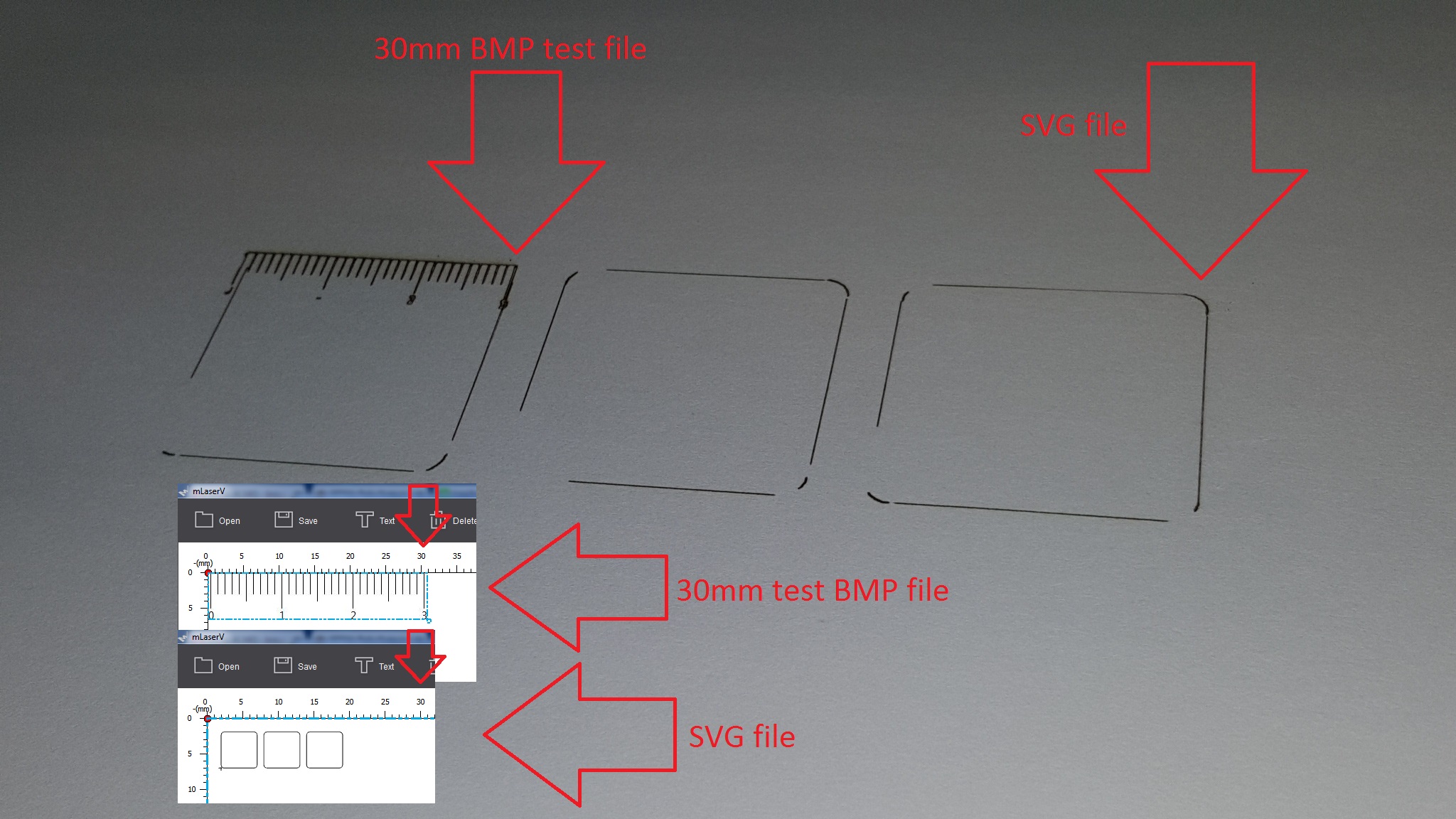
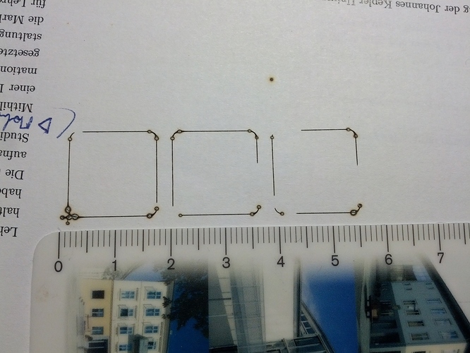
I also tried the 40x40mm test square (I assumed you’d supply a file with a square at that size?..) and scaled it, and got:

hmmm – the software seems to drop waypoints – also, if you look at the first picture, yo can see random dropped segments (all rectangles are closed in the input file) – I reduced travel speed to 800mm/min to rule out mechanical issues.
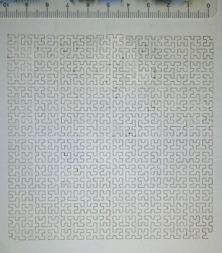
It looks as if it is not a tension issue either, connected tracks print more or less ok:
(svg extracted from from https://en.wikipedia.org/wiki/Space-filling_curve#/media/File:Hilbert_curve.svg )
BUT if you compare you can see missing segments at the beginning and end of the figure, a dropped corner point (bottom left) and a series of dark dots - seemingly communication stalled here?
Does anybody have a serious driver software? Otherwise I’d script my own g-code generator 
S
P.S. mLaser runs on a Windows 10 machine; I compiled the github repo on a Linux Mint machine, but it did not show any data in the preview window. Will retry with another laptop later.

