OMG, I’m sorry for the accident. It’s very strange about the FTDI chip was burnt.
I have posted this to reddit(3Dprinting/Arduino/Robotics) and facebook. Maybe there are some people could help you get the reason.
OMG, I’m sorry for the accident. It’s very strange about the FTDI chip was burnt.
I have posted this to reddit(3Dprinting/Arduino/Robotics) and facebook. Maybe there are some people could help you get the reason.
There is someone ask question on reddit:)
I read your blog about changing stepper drivers and motors. Are you sure you had the pots turned high enough? I have similar spec’d motors to the original ones and they can get hot and hold extremely well. I have the black edition with heat sinks and active cooling though.
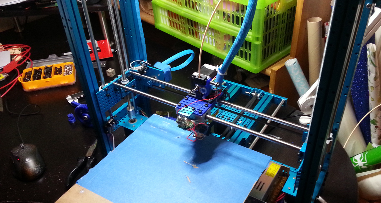
Short day due to meetings, but I got the X-axis up and running. This is the axis that pulls the least weight, so I’m trying to use the original 40N stepper here, along with a 18T pulley. Curious to see how that goes once the printer gets up to speed…
Soldering headers / extending cables also takes quite some time, but it’s getting there. Here’s a short vid showing XYZ homing.
I also received a new set of the Megatronics electronics from Sainsmart. Sainsmart produces loads of hobby electronics at really low prices, but the quality can be varying. This one looked really dodgy and had soldering bridges on the FTDI chip, so I’m unsure how long that’ll last. I removed the bridges and then tested it. The board programs as it should, so I guess I’ll use and see how it goes.
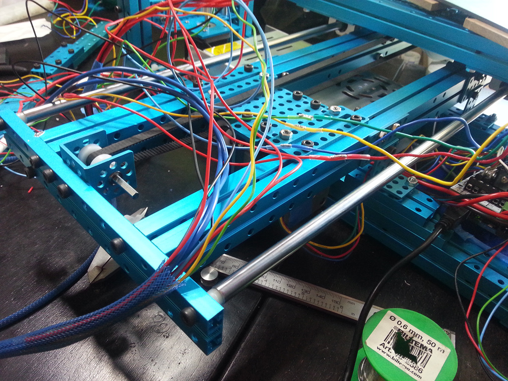
Today was spent mostly on making cables. The two printers I’ve built before have both been nice, premade kits. You don’t think much about it when putting together a kit, but extending and making cables is a big part of the job. In a kit it’s all easy, but when you make it all from scratch, you have to first measure and cut all cables to the right length. If they are too short (like those on the steppers) you’ll have to extend them. Then you must solder and crimp each extension to protect against short curcuits. Along the way, you must not mix up what cables so it all looks like a rather colorful mess.
Here I’m using a clear shrinkwrap when extending cables in stead of the typical black one. I prefer this since it’s easy to inspect a joint later. I could of course just wrap some tape around this “cable spaghetti”, but it looks so much better if you pull a braided sleeve over them. These plastic “socks” will expand to let you pull cables through, but once you let go of them, they tighten up to make your cables look nicely organized.
Note how it looks like spaghetti going in and a nicely organized blue mesh going out as I feed the cables through the sleeve. Before doing this, I put a little bit of crimp on the tip of all cables so that they would not get stuck in the mesh of the sleeve as I pushed the wires through.
When all cables are the correct length, You’ll need to add some kind of receptacles. The most common one on Ramps-electronics are plain old Dupont headers. I’ve soldered and crimped maybe 50 of these thus far. It’s a tedious job, but it makes it so much easier to connect and reconnect and the result looks much better.
With cables made for the extruder’s heater, temperature, fan & stepper (10 alltogether), it was finally time to test it all. Here’s the first plastic extrusion!
As you can see, I need to adjust the power to the extruder-stepper, but a little helping hand got the plastic through. It’s a quick fix, but that can wait until I’m back on Megatronics instead of Ramps 1.4. I’ll try to fasten the bed next so that I can start printing actual models!
Note: it’ll actually be a few days until the next update as I’m tied up at the #ndcoslo conference for a few days.
I like the sleeve! The cables are nicely organized by this.
It seems that the extruder was working very well in the video. Waiting for the first actual model! 
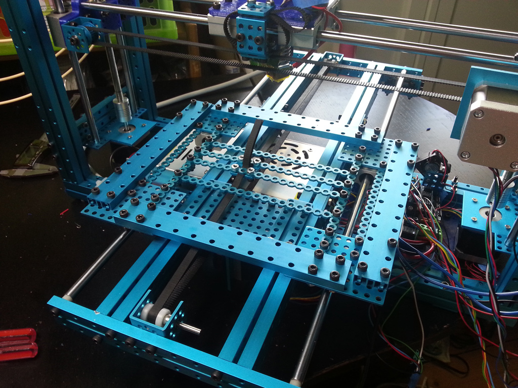
To be able to print, I had to finish the build surface. I changed the moving platform so it’s not using the 2424 beams, but rather normal 0824 beams. This gave me 1,6 cm extra build height, but also reduced the weight of the platform a little. This is how my final platform base looks:
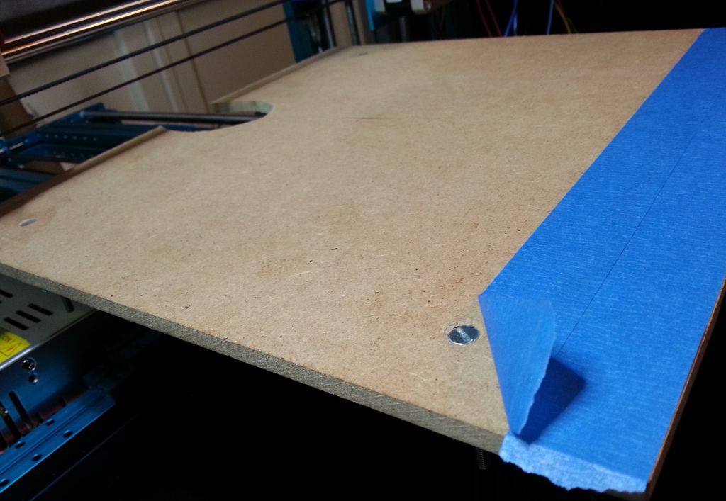
It’s completely stiff and square. Once I had the design of the platform locked down, I could start fastening the MDF board that I have precut to 30x30cm to the aluminium frame. I drilled holes and countersunk the screws.
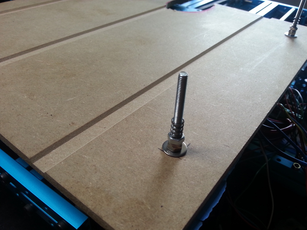
I have some spacers, nuts & a spring that allows me to adjust the distance of the MDF from the platform.
You flip this around and take the screws through the platform base and then secure them with a wing-nut. Once the platform is in place, you cover the MDF with blue painters tape and you’re ready to go.
I’ll need to cut off some centimeters of the screws that hold the platform, but other than that it’s pretty much done. After a little more testing that revealed that I had inverted a couple of the axis, I was ready for the first print.
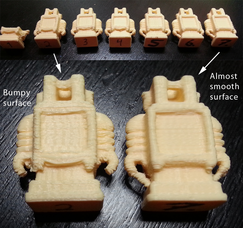
The audio isn’t too good on the video, but the first print failed when I connected a fan (1). Not sure why this disturbed the USB comms enough to cancel the print, but the second printed as it should have (2). This morning I did one at slower speeds and that looks even better (3) but it’s far from the quality I’m after.
As you can see, there’s quite a bit of “ringing” from the belts, even on the last print. I’ll tighten them, keep tweaking the settings and post progress here later.
I’m just back from summer holidays with the family and have had some more evenings to tweak the output. The main build is finished, but I’ll keep updating this thread as I go along.
I’m now at a point where I feel the quality is “good enough”. It’s not perfect, but it’s a really good start. It’s not that apparent in the latest prints, but there is still some vibration in the printer that affects the prints. I’m not 100% sure of what it is, but I am sure that I will solve it over the summer. As can be seen from the image below, I’ve done lots of printing and this is only the ones I kept to show progress. Altogether I’ve probably printed this robot more than 30 times.
Here’s a list of what I’ve done to tweak the quality:
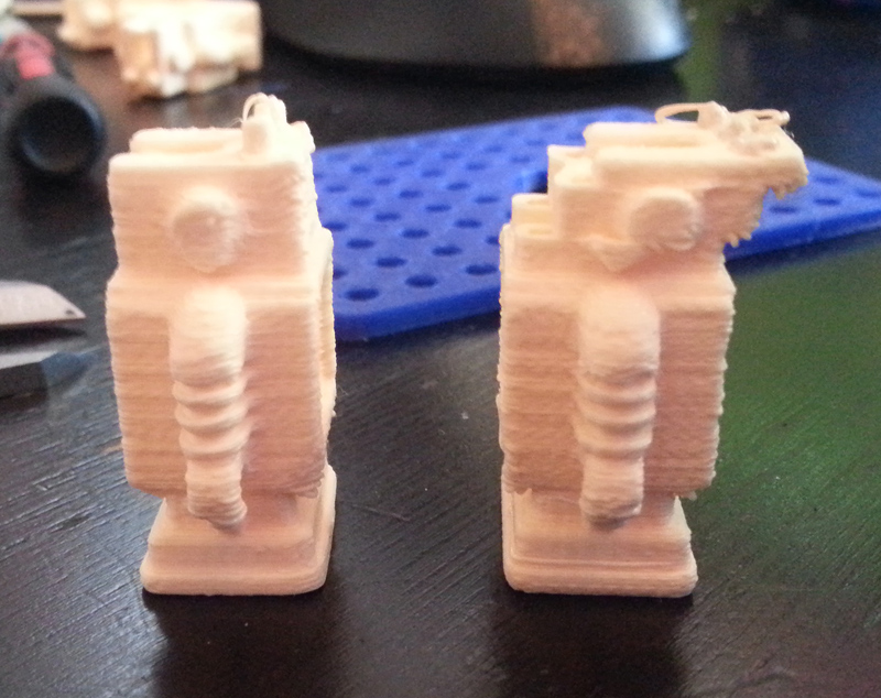
This is how it looks when the X-axis slips at the end of a print.
As you can see, it’s quite easy to identify what has happened, but it’s really annoying when this happens. The stepper should be adjusted so that it does not overheat, but still supplies enough torque so that the motor does not slip. Finding the balance can be a little tricky.
Right now I’m working on shrinking the carriage from 11x11 to 8x11 holes in platform size. The current Wades-based extruder is simply too big. I’m now making a small, compact extruder based on this design that uses a MK8 drive gear instead of a hobbed bolt. If this design works as well as planned, I’ll be able to add a second extruder similar to how it’s done on this Bokubot.
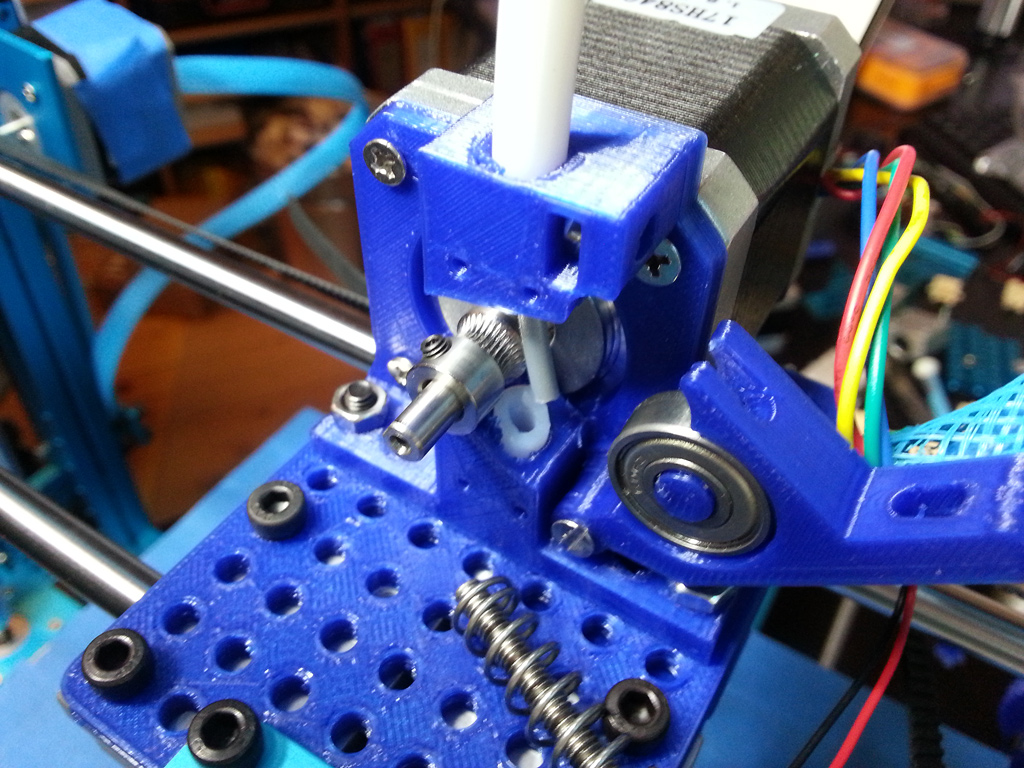
Today I finally nailed the quality issue that have bugged me! Yesterday I completed the design of the new extruder. It is even more compact than I hoped for, so it only takes up 7x11 holes!
The MK8 extruder wheel is really compact and the material idles against this and the bearing. Note the white PTFE tube leading both into and out of the extruder. This will ensure that soft materials slide with as little friction as possible.
The 3D files for the extruder are now up on my Youmagine account, so feel free to download if you want. After todays upgrade of the Z-axis, these are also the only printed parts in the design. Apart from electronics and the E3D hotend, the rest is all Makeblock parts! The fully adjusted firmware for the Megatronics are also updated on my Github page.
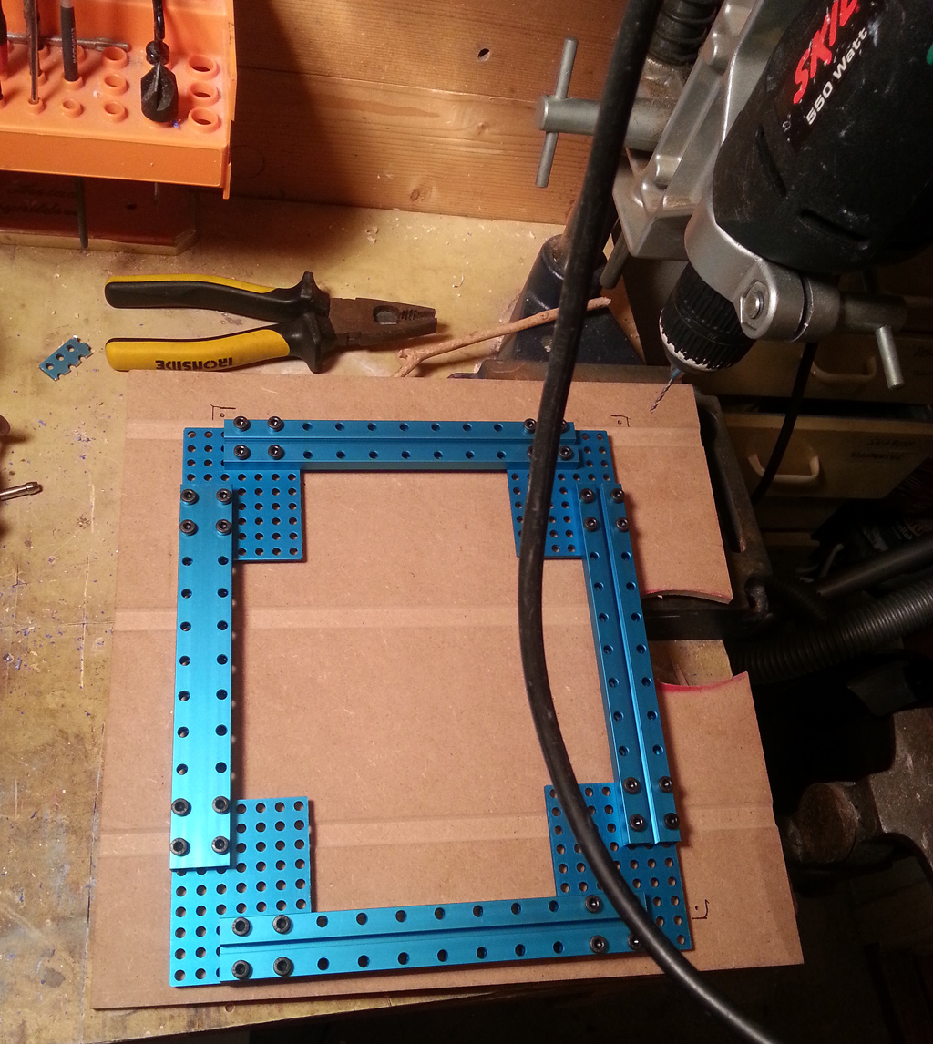
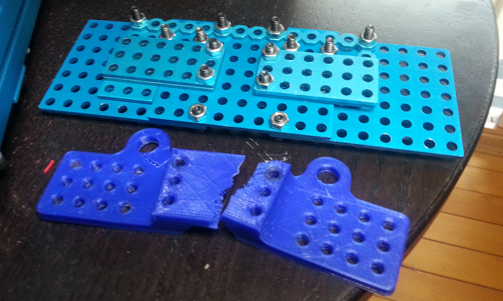
Designing and testing the extruder took a full day and today was spent on changing the entire Z-axis. I initially tried to make this axis using Makeblock parts, but at the time I was low on 7x9 plates so I didn’t find a solution that worked. Instead I modelled and printed some brackets and now they were breaking up.
I did maybe 6 different solutions until settling on the one above the broken plastic part. The new design forced me to cut the linear rods again. Easily done with a Dremel and a cutting disc.
Note that I’m only cutting one end, so I’m keeping the threads on the other side. I had to clamp the long nut with a 3x6 plate as well as secure it with zip’s but the end result is now really solid. I’ll need to tweak the cables on the extruder a little, but I’m very happy with the overall looks now.
Lots of things had to be changed to make this possible, but the end result was really worth it since the wobblyness in all prints are now completely gone! Just look at this:
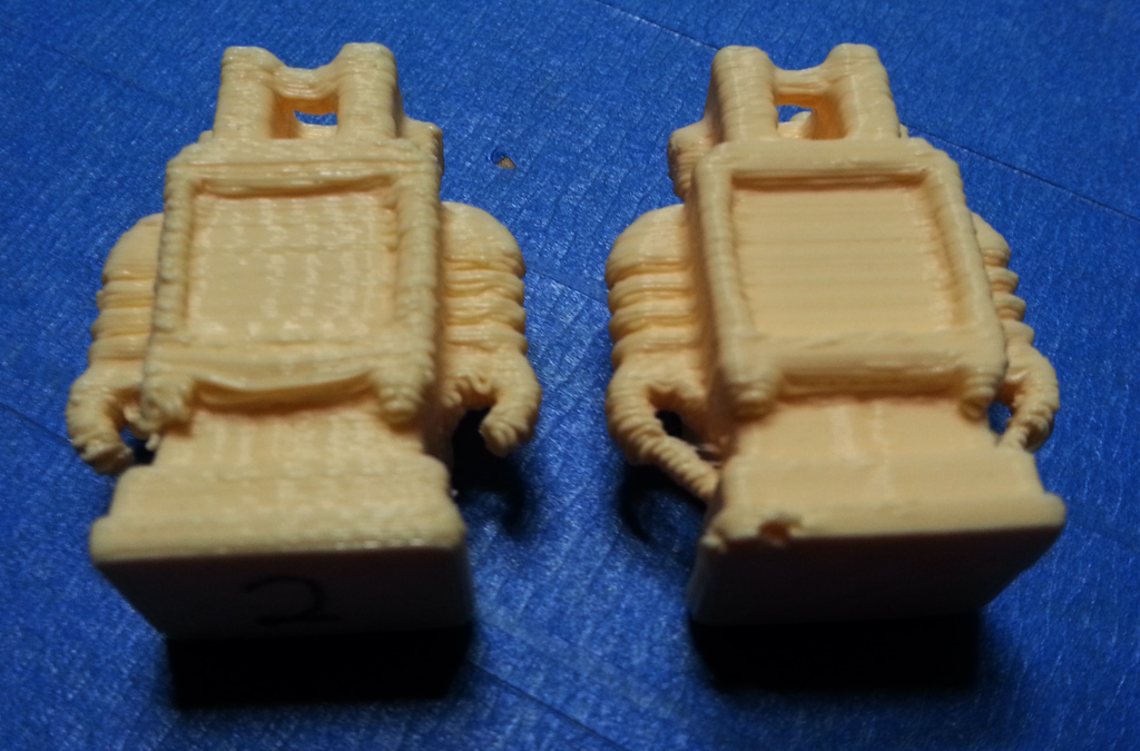
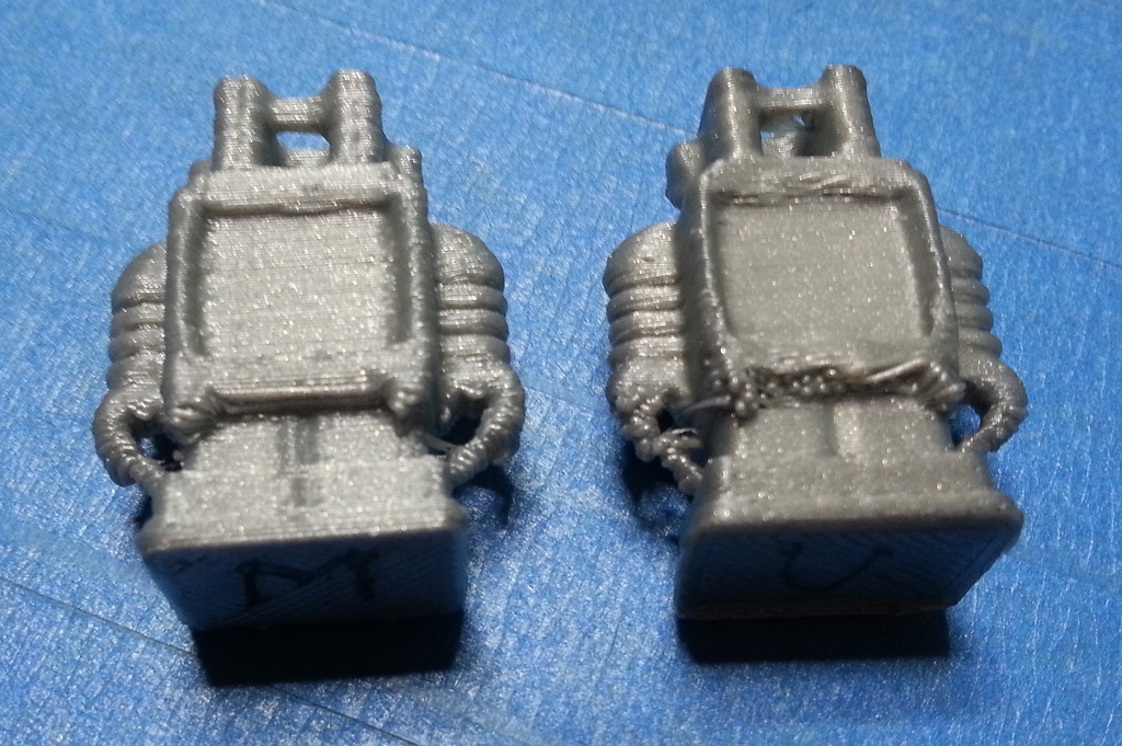
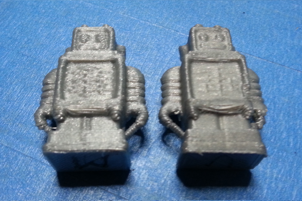
This looks MUCH better, doesn’t it? Next up I wanted to compare it with the Ultimaker!
Wow! The Makeblock-printed robot (M on the bottom) looks BETTER than the Ultimaker (U on the bottom)? That I did not expect at all. Let’s have a look at the front?
Aha… That made me sober again. While the UM is sagging more, it has a lot more of fine detail on the front. It’s not that much of a difference though and I’m sure I can get it close by just tightening the belts a little more.
Another good thing about the rebuild - the Z-axis now extends to 34 cm! That gives the printer a total build volume of 32600 cm2 (31 x 31 x 34 cm). Not bad and above what I aimed for! I’v summed up all the advantages of the printer design in this blog post. Can’t think of any disadvantages yet 
I’m rather confident that this is my final design, so I’ve started working on the Bill Of Materials (BOM) in case others want to build a similar printer. After this I’ll tighten up some cables, add an external controller for USB-free printing and set up the heated build surface.
Here’s a video of it printing!
Hello,
first thanks for sharing all this!
I understand the ‘need for speed’ when 3D printing, definitely for commercial applications, but i wonder if quality can be improved by slowing it down ?
I would consider buying this, but will probably wait until there is a 3D printer that has Lego quality. (which is around 2 to 20 micrometer). Are you reaching around 500 micrometer now ?
cheers,
paul
Hi Paul,
These kind of (FDM) printers can easily print 0.05mm layers if you need that. The models above are all printed with 0.2mm layers. Each robot takes 28 minutes. At 0.05mm layers, that would take about 2hrs per robot since layer height vs print time is linear. 0.025mm layers are also possible, but would take double.
By printing with ABS plastic, you’d get something that is very comparable to LEGO, but it would have only 40% the strength of an injection moulded part.
you would still see the layers though, so if that is important, you should look at SLA printers instead. I just signed up for this one : https://www.kickstarter.com/projects/kudo3d/titan-1-fastest-tallest-print-high-res-sla-3d-prin/posts/885097
J
… and yes - going slower would improve quality a bit. There is a limit though since the printer uses belts moving a fairly heavy stepper motor. Due to the mass, changes in direction will cause a little stretching of the almost 80cm long belts & produce inaccuracies throughout the print.
J
Hi all,
It’s been a while since I updated this thread, but things are progressing along nicely. The printer also has a name! I’m calling it “BAMM” (Big Alu Makeblock Mendel).
I have made a first version of the Wiki page that has a full Bill Of Materials (BOM) for others that want to build the same or a similar printer: http://wiki.makeblock.cc/index.php?title=3D_Printer_@Jenschr As can be seen from the BOM, the price of all the components (aluminium, electronics and the rest) are just below $1100.
That’s actually a really good price? It is two thirds of the price for the Ultimaker Original kit (the printer I’m replacing) and almost one third the price of an (assembled) Makerbot Replicator, so that’s not bad for a printer that can go bigger & hotter with more material types & less noise?
Next up is to work out some way to make build instructions without spending too many days on it. I’ll eventually make a 3D model and use snapshots of that, but that’ll take more time than I have at the moment. I guess that taking some more pictures is the easiest way to document. If anyone is building - feel free to ask me questions via this thread.
The printer now has a much improved extruder design, a custom controller (for computerless printing) and a heated bed. I initially was sent an incorrect heated bed (300x300mm) for AC voltage, so I had to purchase another one that was for 12V DC. The new one heats up really fast despite being just 12V (0-60C in 3 min).
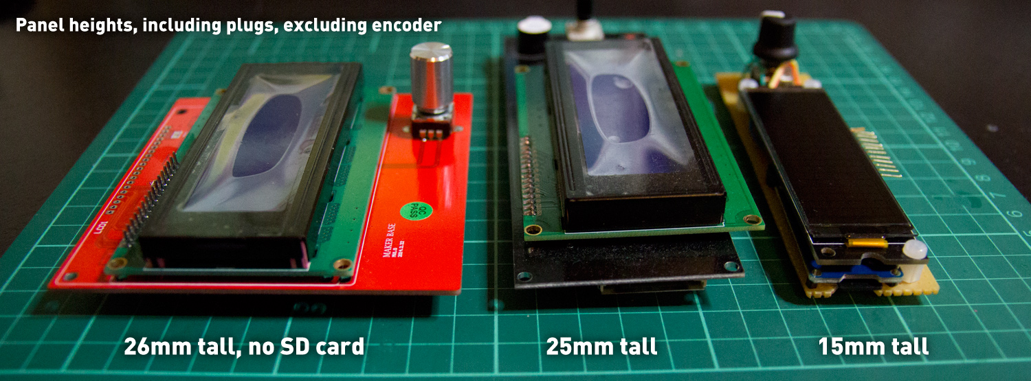
While I’m at it - I’ll explain why I spent time building my own controller. Have a look at these pictures:
The first two came with the Megatronics 2 kits that I purchased. They will both work (#1 only with software modifications), but have a look at the size? By simply putting a SD card reader, a buzzer, encoder and an OLED screen on a perforated board, I’m able to make something much smaller and better looking?
The OLED has superior visibility compared to a normal LED screen, but it’s also much flatter and uses less energy. Hacking this together in software took some time, but now I’ve written a guide for others that want to do it. You can find it at my blog. That’ll make it easier to make custom controllers using ANY screen and not be limited to these thick & clumsy old LED displays.
J
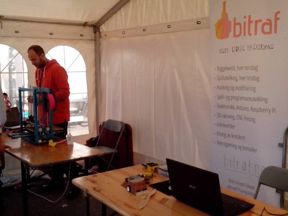
A few weeks ago, I travelled 500 kilometers to show the printer at the Trondheim Maker Faire. I managed to pack the printer inside a normal suitcase! It was great fun to be there and many were really curious about the printer.
After two days at the Maker Faire I went home and the printer survived the two plane trips impressively well. With only a few broken limit switches after travelling as airline luggage, I assume that we can call it a solid printer
As soon as I got home I started solving issues and the by far biggest one has been the inability to print PLA. ABS & PET plastic printed without any problem, but PLA (the one I use the most) would always get stuck and block the extruder. After a lot of discussion on the E3D forums, I’ve nailed it down to the fact that my pinch-extruder does not have enough torque to push the plastic through the all-metal hotend.
It’s actually so many other things I’ve done since the last update so I shot a video that shows the printer as well as the many upgrades.
Here’s the list if you don’t want to watch that long video:
That’s it for now. My current plan is to upgrade to mount the controller, add the Bulldog XL extruder as well as test more materials such as NinjaFlex & Nylon!
Here’s some material testing updates on my Blog & Tumblr
Mounting the BulldogXL extruder:
Printing with NinjaFlex (soft filament):
Printing with PET+ from MadeSolid:
http://flashgamer.com/arduino/comments/testing-pet-from-madesolid
Comparing the E3D & Hexagon hotends:
The extruder has been changed so the nozzle is now in front of the carriage. This provides easier access to the nozzle for maintenance/cleaning and also makes room for a small lightsource to show the print. I put four 5mm LED’s there with a pot for dimming and with the tiny 12V breakout beneath the extruder, it’s quite easy to add stuff like this. I’m also extremely happy with the BulldogXL extruder & Hexagon hotend combo from Reprapdiscount. I keep playing around with exotic materials and the extruder setup works flawlessly.
The 7 x 14 hole baseplate for the carriage is printed in carbon fibre PLA from Proto-Pasta for extra rigidity and is strengthened further with a 7x9 aluminium plate. I modeled the parts in Rhino and the STL-files are now up on my YouMagine page.
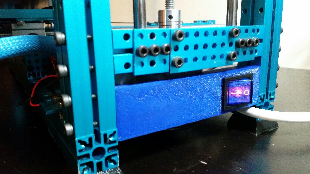
All wires now have proper connectors, the 220V power cord has a proper switch and the extruder uses a smaller fan that fits beneath the carriage. The extruder, wires & hotend now fits snugly inside the baseplate, making it fully possible to mount a second extruder! As usual, there’s more pictures from the build on my Tumblr.
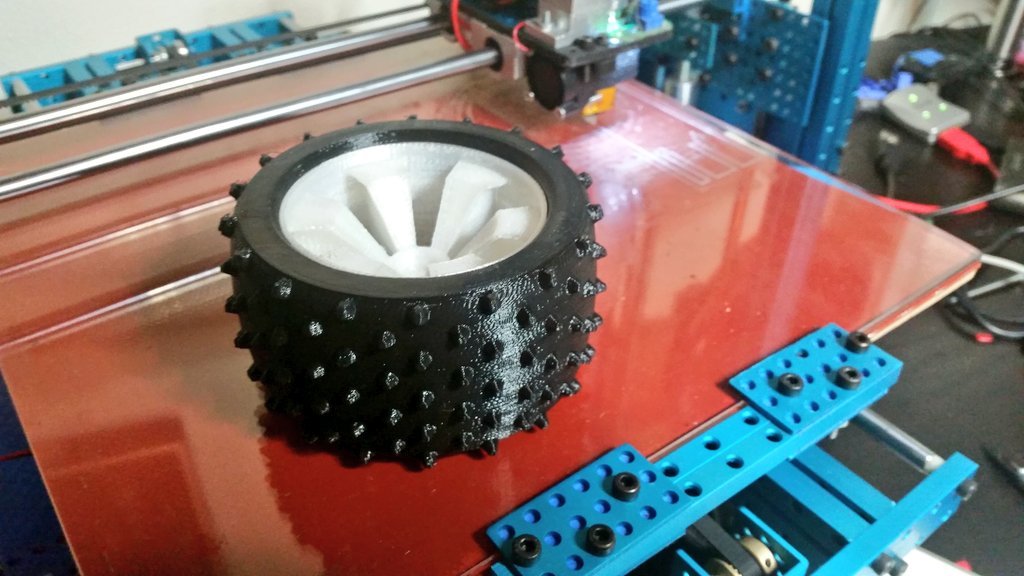
It’s been a while since the last update. One reason is that the printer is working beautifully & the other is that I’m consulting more these days. One of my favorite prints is this wheel for an 1:10 RC car. The rubber is printed in black NinjaFlex & the rim is printed in Taulman 645 Nylon. Both these materials are extremely durable. The Nylon will never break, despite using a sledge-hammer. The Rubber can be torn apart, but it’s impossible unless you use extreme tools such as a knife or something similar:
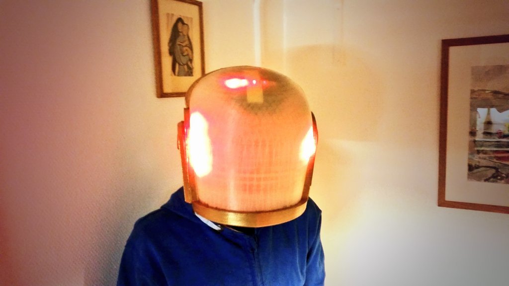
Another favorite is a Daft Punk helmet that I printed for my son. He then added some blinky LED’s & a microcontroller inside so it looks crazy cool! This is the biggest print I’ve done this far. It’s 25 x 25 x 22 cm and fits my head nicely as well. It took 34 hours to print and there’s not a single error/defect:
You can see more prints such as a 35 cm long tube on my Tumblr account
A small update, I just finished a 69 hour print without a single failure
The print is Baymax’s helmet from the movie Big Hero 6, created by Pachyy on Thingiverse. More pictures from the print here, and here’s a video update on what I’ve done on the printer lately: