Q1: Why does my PC fail to install the makeblock MegaPi Driver?
A:For MegaPi, the main control chip is Mega2560 and driver chip is CH340. For some computers, the driver may not be automatically installed, so you have to install the Driver manually.
The complete installation process of Arduino and driver is as below. (Note: You may skip the steps for installing Arduino, and only install CH340 driver)
Arduino is an open-source platform based on easy-to-use hardware and software. It includes a development environment (IDE) and library. The IDE is written in Java and based on processing environment. We provide a complete Arduino development environment for users.
Step 1: Download Arduino IDE and install Arduino driver
Arduino IDE installation package: Windows / Mac OSX / Linux ( 32Bit | 64Bit )
Arduino driver:
Windows : Download
Mac OSX : Me Baseboard / Makeblock Orion(CH340 driver, compatible with MegaPi mainboard) / Arduino Uno
Step2: Install Makeblock Library for Arduino
(Note: The Arduino installation package for windows has integrated the Makeblock library.)
1.Download the library zip package here.
2. Decompress the makeblock folder in the zip to the Arduino default library:
Windows 7: “[arduino installation directory]\libraries”Your Arduino library folder now looks like this (on Windows):
[arduino installation directory]\libraries\makeblock\src
[arduino installation directory]\libraries\makeblock\example
…
or like this (on Mac):
[arduino directory]\Contents\Java\libraries\makeblock\src
[arduino directory]\Contents\Javalibraries\makeblock\example
…
or similarly for Linux.
3. Open Arduino IDE. If it is opened, you need to restart to see changes.
4. Click “File->Examples” to check sample code under Makeblock folder.
Q2: Why is the suite complete with video building course?
A: That is because it is Geek suite so that video display is more vivid and detailed. 3D model may be used to check assembly details, please click this hyperlink to check or download 3D model.
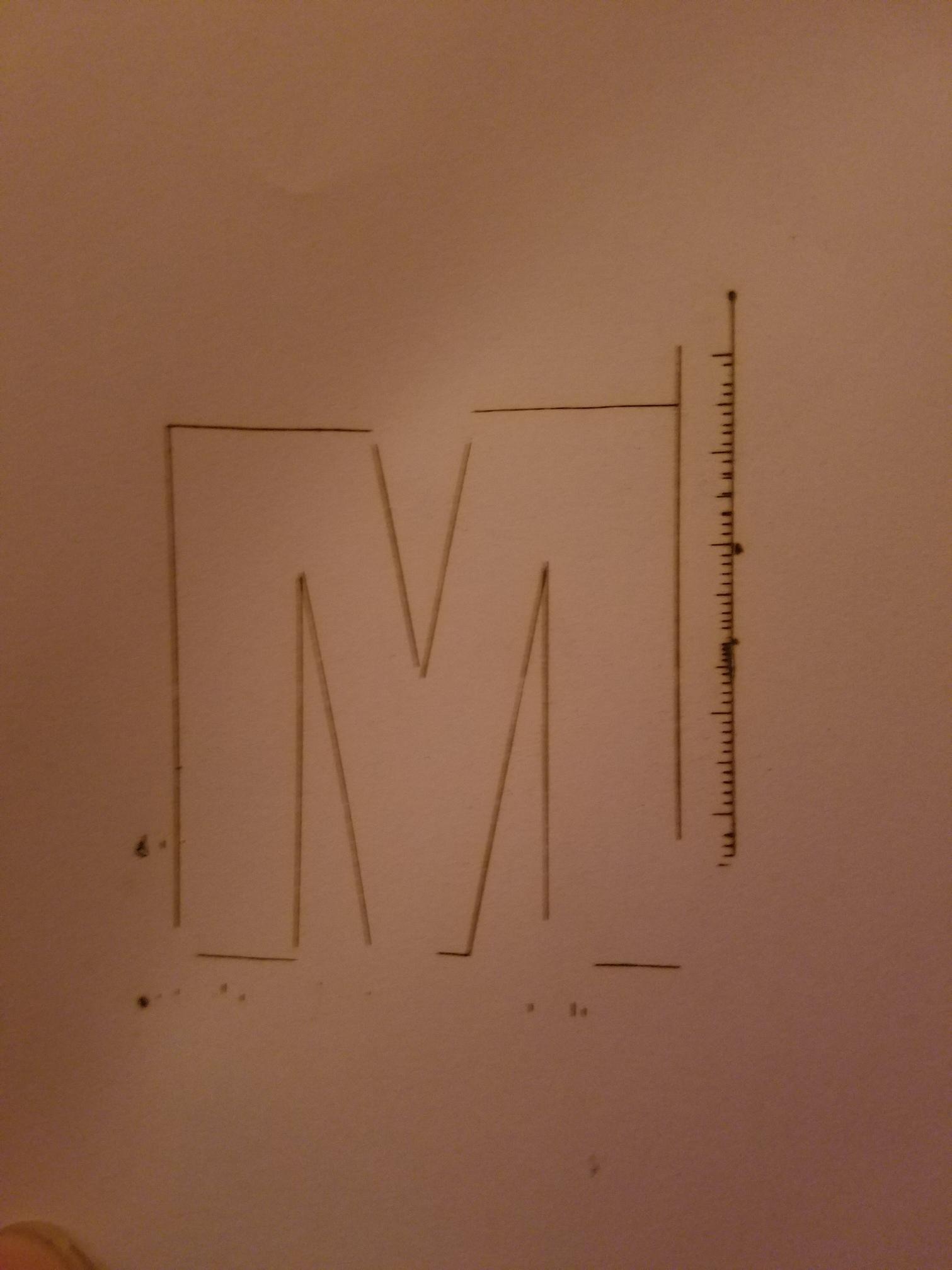
Q3: How can I adjust the precision if it is not sufficient in the laser-engraving image?
A: A file of standard square may be imported for test. The test method is as below.
-
Click this hyperlink to download test file
-
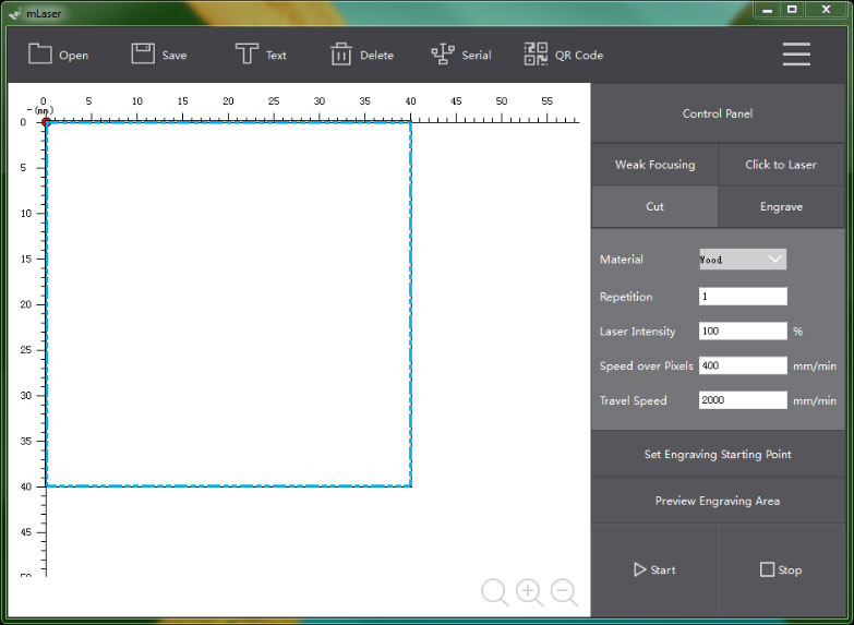
Start mLaser software, enter it and switch to the advanced mode. Click three-bar icon→interface selection→advanced mode at the top right of the software.
-
Open→Square Test.svg→adjust the size to be 40×40 mm.
-
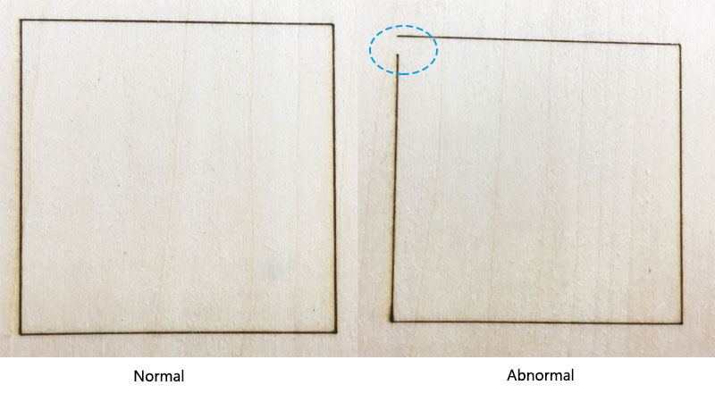
Set the laser parameters and the engraving starting point. Use frame preview function to adjust position. Then click “start” to start engraving. The comparison of normal and abnormal cases is as below. The abnormal case has such problems as deformation, parralellagram and incorrect length-width ratio.
-
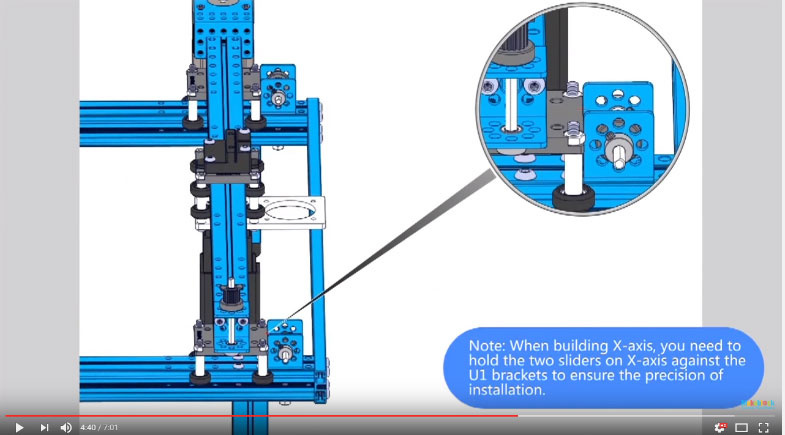
Generation of abnormal engraving images is mainly due to failure of LaserBot to strictly comply with video course in the building process, thus causing X axis and Y axis to be not vertical, and timing belt drive to be loosening and not be synchronous. The troubleshooting is as below:
5.1 Adjust installation of X and Y axis to make them vertical, as seen in notes at 4:40 in the building video.
5.2 Initial tensioning may be done when Y-axis timing belt is tensioned. Choose U bracket as a referrence at the time of final tensioning to make the two timing belts locked tightly and moving synchronously. Y-axis is perpendicular to X-axis. This part may need repeated adjustments to ensue precision.
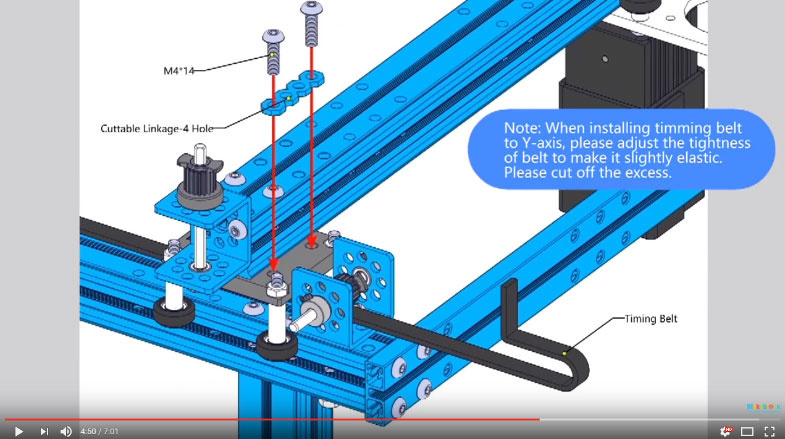
5.3 The timing belt of X-axis and Y-axis shall be properly tight so that the tensioned timing belt is slightly elastic. The M3 set screws of 6 timing belt wheels are required to be locked tightly, or slip may occur, thus causing loss in machine precision. As 512 mm × 4 mm shaft on Y-axis is used for guaranteeing synchronous driving, the 2 18T timing belt wheel on it require adjustment and tight locking. (Locking shall guarantee verticality and uniformity of Y-axix and X-axis)
5.4 X-axis and Y-axis roller shall be installed to guarantee smoothness and proper tightness. Smoothness means smooth slip without any blockage, while proper tightness means tightly locked screws and that slider does not shake. All these require careful adjustment. Please make adjustment patiently.
5.5 After the above adjustments, get the laser head to manually slide within the operation range to check smoothness. If it is less smooth, adjust it again.
5.6 Repeat steps 1, 2 3, 4 under this question, until a normal square is drawn.
Q4: Normal upgrading of firmware is not possible for mLaser.
A: If firmware cannot be abnormally burnt during use, re-plug USB. If there is not any serial port, please install CH340 driver in the way as mentioned in Q1, and then burn the firmware. If the firmware remains not to be burnt, it is suggested to restart the computer or contact the customer service through tec-support@makeblock.com.
Q5: Why does mLaser not well support DXF format?
A: That is because DXF is complicated. The existing mLaser software makes abnormal opening of DXF format generated directly. It is suggested to use *.svg or transform into the common format *.svg.
Q6: Why does mLaser opening file have a large bounding frame and how can this problem be solved?
A: Current mLaser edition displays SVG file in a similar way that browser opens SVG files, so displaying effect is not different. Specific method for obtaining SVG file with a displaying effect of final wireframe format is as below.
-
Download and install inkscape software.
-
Reserve displaying way of wireframe only
2.1 Select files, click the button X at the lower left corner of Inkscape interface for removing the filling content.
2.2 Check→display→wireframe for changing display into wireframe mode.
2.3 Recommended saving format: file→save-as→save-as format→common SVG format (*.svg)→save
Q7: How can files of vector format such as AI.Coreldraw and CAD be converted into SVG files?
A: The Internet may be used for search of relevant introductions. The general method is to save vector format as general format, such as dxf. Then use Coreldraw software to open and save as Coreldraw format. Then open it with inkscape and convert the format in the way as mentioned in Q6.
Q8: What is G-code format of mLaser?
A:The standard G-code instructions used in LaserBot
The standard G-code instructions used in LaserBot, show on table below:
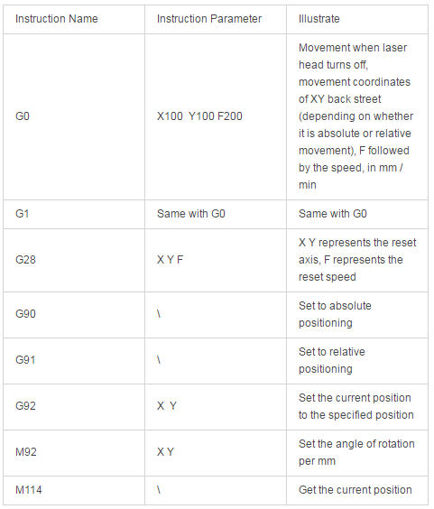
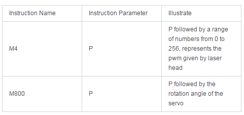
Customized Gcode instructions set in LaserBot
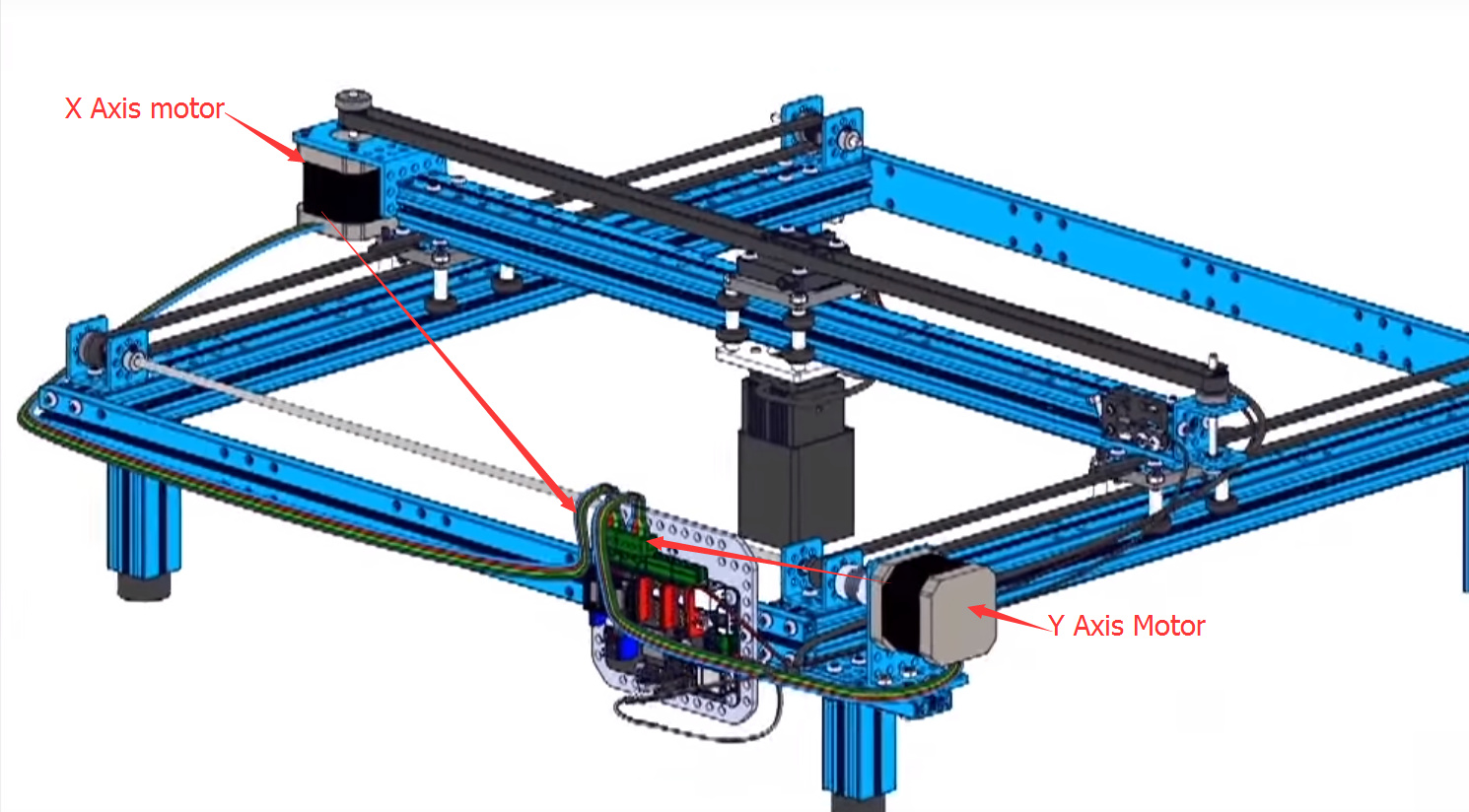
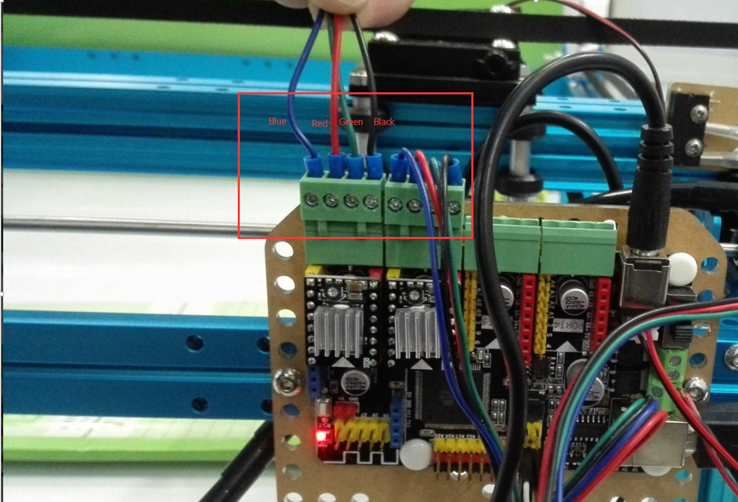
Q9: If LaserBot built in accordance with LaserBot Builing Video is found not to be consistent with the right running direction of the software, how can I solve this problem?
A: It is a rare situation. It is generally a result of incorrect factory default direction of stepping motor. Please find out the stepping motor which runs in opposite direction and whose default wiring order is black, green, red and blue. Then you may change the wiring order to change the running direction of stepping motor to be green, black, red and blue, for instance.
For more info of Laserbot, please visit our Learn website.