Hello Makeblock Community!
Everything I show you, I have tried for myself, on the Me Auriga, Me Orion and the MegaPi Shield for RJ25.
Although I wouldn’t recommend the MegaPi for mBlock, since it isn’t fully compatible with mBlock.
Recently I got the Me Angular Sensor and wanted to use it in mBlock.
Since I couldn’t find any information on how to do this, I spent a whole weekend on figuring this out, by myself.
Perhaps this information is useful to others, who also want to use Me Angular Sensor in mBlock.
I am still very new to mBlock/Scratch/Arduino/electronics, so I am very grateful to anybody, who points out any mistakes/errors I have made.
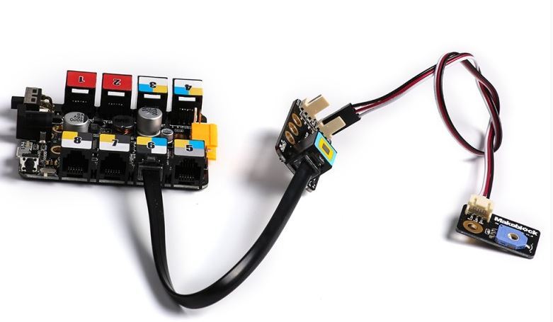
First you need to connect Me Angular Sensor to Me RJ25 Adapter.
You can connect up to two Me Angular Senors to one single Me RJ25 Adapter.
Best is to the establish a connection between your board (i.e. Auriga, Orion, or Megapi) and the
mBlock-program, before you connect the RJ25 Adapter with the board.
You need to connect to a port on the board with black color indicator, since its an analog sensor you want to connect, and black is the color for analog ports.
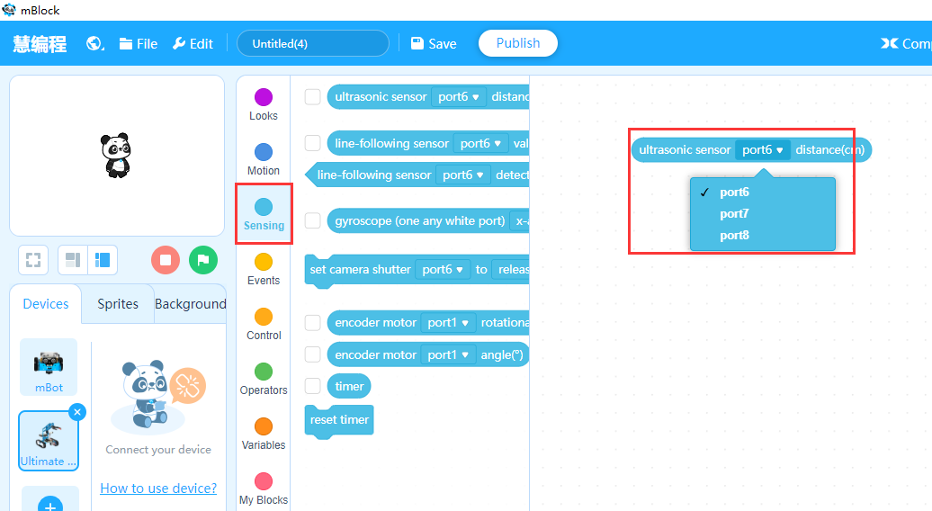
In my example I will always use port 6, since is a black port on all 3 boards (Auriga, Orion, MegaPi) I have tried.
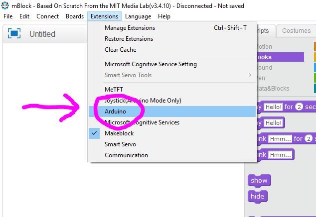
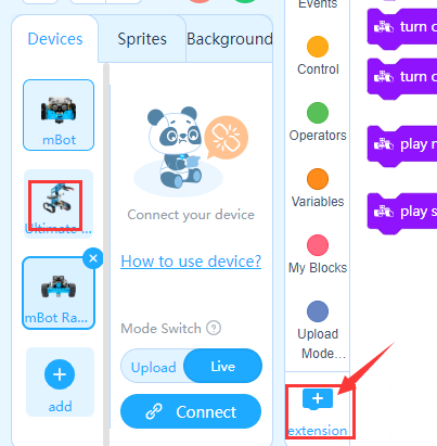
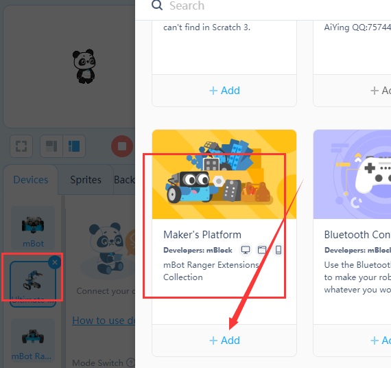
In the mBlock-program, you have to enable the Arduino Extension, like in the picture above.
.

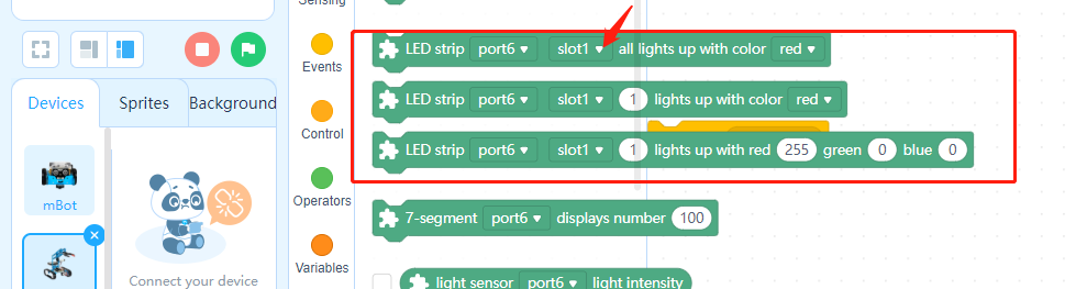
Then you can use the “read analog pin (A)” block in your program.
How to find out the value to use in the “read analog pin (A)” block:
That’s very easy if you have the pinout for your board.
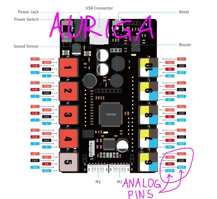
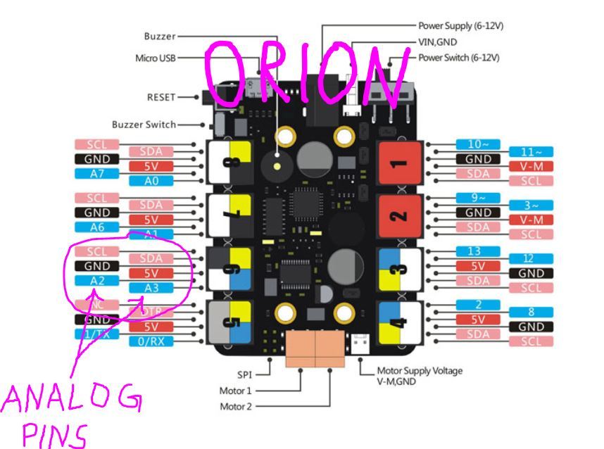
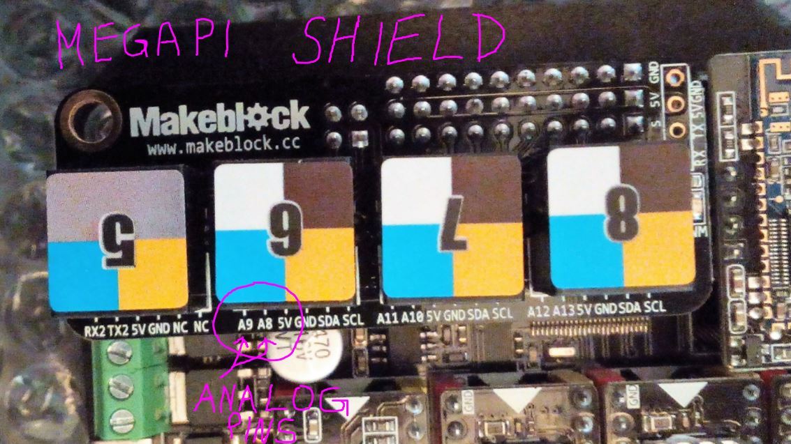
So here are the pinout for the Me Auriga, Me Orion, and for the MegaPi Shield.
I have marked the relevant analog pin numbers for port 6, on every picture, as an example.
.
So for our example you have connected the Me RJ25 Adapter to port 6 on your board.
If you use the Me Auriga:
You use the value “10” as input for the “read analog pin (A)” block in your mBlock-program to read the Sensor connected to slot 1 on the Me RJ25 Adapter.
And you use the value “15” as input for the “read analog pin (A)” block in your mBlock-program to read the Sensor connected to slot 2 on the Me RJ25 Adapter.
If you use the Orion:
You use the value “2” as input for the “read analog pin (A)” block in your mBlock-program to read the Sensor connected to slot 1 on the Me RJ25 Adapter.
And you use the value “3” as input for the “read analog pin (A)” block in your mBlock-program to read the Sensor connected to slot 2 on the Me RJ25 Adapter.
If you use the MegaPi Shield:
You use the value “8” as input for the “read analog pin (A)” block in your mBlock-program to read the Sensor connected to slot 1 on the Me RJ25 Adapter.
And you use the value “9” as input for the “read analog pin (A)” block in your mBlock-program to read the Sensor connected to slot 2 on the Me RJ25 Adapter.
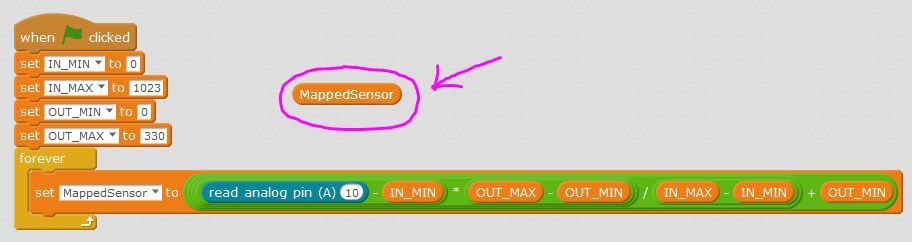
How to map the Me Angular Sensor in mBlock:
After you have successfully connected the Me Angular Sensor to your board and mBlock,
you will find that it only outputs values from 0 to 1023, and not the 0 to 330 degrees its made for.
So to get the correct values from your Sensor you have to use this formula. I think its
pretty much self explanatory, but:
IN_MIN is the lowest value you can get from your Sensor,
IN_MAX is the highest value you can get from your Sensor,
OUT_MIN is the lowest value you want to use for measurement,
OUT_MAX is the highest value you want to use for measurement.
.
.
Sensor Value Mapping Function.sb2 (48.6 KB)
Now you should have a Angular Sensor that shows the correct values in mBlock.
I hope this information will be a help, to anybody who wants to use the Angular sensor in mBlock.