XY Plotter - Y Home Position Failure


#1

@tec_support

Recently assembled an XY Plotter, started mDraw (ver 1.2.1), updated firmware using ‘Update Firmware’ button, and attempted to go home. The X-axis homes to the zero position; however, the Y-axis does not move.

Tested all the limit switches under the tools/settings button all read 1 when not pressed and read 0 when pressed.

Turned off stepper motor controller, manually moved to the Y-axis limit switch, loaded several drawings, hit the play button, and all worked fine. Tried to ‘Home’ the XY Plotter; yet, only the X-axis proceeded home.

Is there something I missed?

Thank you for your assistance in advance.


#2

Hi xyberpunk,
The mDraw software may have remembered other position as the Home position.
Normally, the mDraw software remembers the current position when you power on the XY Plotter which connected to mDraw as the original position. Please try following steps to test Home.

  1. power off the XY plotter
  2. Move the carriage to the position (x=0, y=0)
  3. Power on the XY Plotter and connect the Serial port of XY plotter on mDraw. (Now the software will remember the position x=0, y=0 as the Original position).
  4. You can click on the other position on mDraw, the carriage will move the other position, then click on Home button, it will go back to Original position (x=0, y=0).

Once it is still the issue when you follow above steps, please kindly take a video to show the behaves on the XY plotter when it goes to Home.


#3

Thank you for the quick reply; however, the solution did not work in my case - but, there is a ‘fix’ that I came up with, see below.

Started troubleshooting the electronics to determine my issue, basically what I found:

  1. Checked the limit switch connections to the ensure they were in the correct position - they were.
  2. Verified that all limit switches for operation using the continuity check with my DMM (digital multi-meter - all were good
  3. Swapped positions with all switches and manually engaged them and watched the settings screen - they all worked
  4. Measured the voltage on all switches; i.e. Gnd to S1 and Gnd to S2 (end-effector moved to center work envelop)
  • X-axis switches measured 4.95vdc in open position, 0.00vdc (approx) in closed position
  • Y-axis switches measured 4.95vdc on S1 in open position, while S2 measured 2.575vdc in open position - BAD!
  • S2 voltage is on the low end of ‘1’ in TTL logic. Traced back from ‘Me RJ25’ adapter to J3, to ATmega328-AU
  • U3 (ATmega328) pin 16 is D12/MISO pin, PCINT4 (interrupt pin) had the same voltage with no logic ckts between
  • Placed a 3Kohm resistor between Vcc and S2
  • Pressed the home position and it worked! WhooHoo!!!
  • Measured the voltage at the pin with S2 open it was 3.63vdc

Overall, there is something sinking some current and dropping the voltage - uhgg. Currently this is a band-aid until I can find the source of the problem, maybe it is the PCBA or some other intrinsic problem with the PIN MUX electronics. If I find it, I will repost.

My main concern is in the case of a power failure and I want to re-home without human intervention. Using the method described above will ensure home capabilities at all times.


#4

Wow, you have done a lot of research. Great Job!
While this is the first feedback for this issue, we will record it and provide feedback to related department. Thanks!


#5

I have the exact same issue with the home function only working in the x-axis, and all limit switches function as expected. Is there a solution that does not involve adding a resistor?


#6

Hi, exploremore,

What was measured voltage on the S2 pin of your RJ25 adapter when the Y axis limit switches was opened?

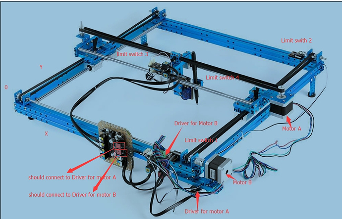
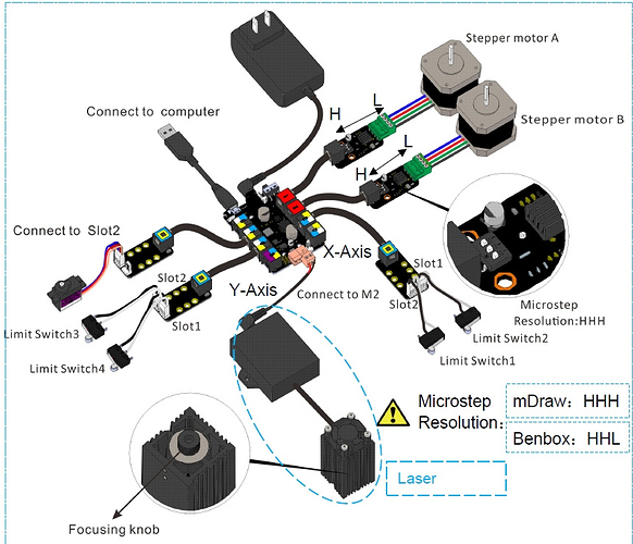
Besides, I wonder if all the wires connections on the XY plotter are connected correctly and properly. Here are two pictures to you for reference, please double check wiring connections on your plotter refer to it properly:


If it is possible, hope you can take a video to show your operations and the behaves on the XY plotter.


#7

Hello exploremore,

Sorry for the late reply. Actually, I have not found the source of the voltage pull down on the board. Possible sources are the PCBA or the actual chip itself.

If it is the chip there may be several things:

  • The GPIO pin is configured incorrectly in the code (for instance it is an analog pin instead of a digital pin and it is emitting a pulse train)

  • Sometimes there is a ‘special adopt’ when semiconductor manufacturers make parts - this may be one of those times.

  • ESD Damage…

Obviously there is a problem still on my board, however, time has been limited in troubleshooting it.

By the way, have you had a chance to do some voltage measurements?

Regards…


#8