[XY 2.02.] why is Y limit switch so noisy?


#1

Hello,

I have bought about 6 units of XY 2.02 plotter kit a few months ago. We strongly modified the original hardware design to make a somehow more compact version of the plotter.

In the original firmware there was no mecanism to return to home. Only the firmware was checking for the limit switch so that the motors could not force “outside the boundaries”. and I had not had to implemented a “go back home” function myself until recently

In parallel, we have pushed the numbers so that the plotter would move faster. We do not know if it is related to our problem, but still worth mentionning i guess.

Some users reported that sometimes it would look like there would me missed steps. We tought it would be caused by us pushing the steppers too much compared to the inertia of the moving parts.
Until one user simply unplugged all 4 limit switches and reported that this problem almost entirely vanished.

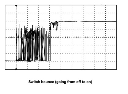
I trying to implement the goHome() function myself now. The code works, but surprisingly, the limit switches on Y axis reports false positives. I other words the digitalRead(mypin) claims the switch is on, while it is not.
That issues does not seem to happen at all on X limit switches.

I have implemented the following debounces strategy for my homing function (firmware based on the much cleaner xybot.ino of mDraw)… but it is not sufficient

// will return the digitialRead value read consecutively "count" times with 10ms between each read
int digitalReadDebounce(int pin, int count = 50) {
  bool done = false;
  int c = 0;
  int previous_status = -1;
  int current_status = -1;
  int i = 0;
  while(!done) {
    current_status = digitalRead(pin);
    if (current_status == previous_status || previous_status == -1 ) {
      c++;
    } else {
      c = 0;
    }
    done = c >= count;
    i++;
    delayMicroseconds(10);
  }
  //Serial.print("status_"); Serial.print(pin);  Serial.print("=");   Serial.print(current_status); Serial.print(" "); Serial.print("i="); Serial.print(i); Serial.print("\n");
  return current_status;
}

void goHome()
{
    goHomeOnce();
}

void goHomeOnce()
{

  // stop on either endstop touches 
  // when digital read is 0 => connection
  //                      1 => disconnection
  
  bool done = false;
  bool x_done = false;
  bool y_done = false;
  
  echoEndStop();
  while(!x_done || !y_done) {
    if (!x_done) {
      if (digitalReadDebounce(xlimit_min)==1 && digitalReadDebounce(xlimit_max)==1) {
        stepperMoveA(motorAbk); // to reach to left corner, we go backwards on X
      } else {
        Serial.println("Done X");
        x_done = true;
      }
    }
    if (!y_done) {
      if (digitalReadDebounce(ylimit_min)==1 && digitalReadDebounce(ylimit_max)==1) {
          stepperMoveB(motorBfw); // but forward on Y
      } else {
          Serial.println("Done Y");
          y_done = true;
      }
    }
    delayMicroseconds(stepdelay_min/10);
  }
  
  posA = 0;
  posB = 0;
  curX = 0;
  curY = 0;
}

both
digitalReadDebounce(ylimit_min)
digitalReadDebounce(ylimit_max)
keep reading wrong values and i dont know why

I have double check all connections
I have tried to move slower

nothing works

anyone has any idea ?


#2

You would be better off using photo-interruptors than mechanical switches. It would relieve voltage bounces from the contacts.

Perhaps the Me Line Follower could be mounted to detect a black plate actuator on your mechnism?


#3

Perhaps the switches are being affected by vibrations transmitted through the metal framework and fibre mounting pads. Try mounting the switches on rubber blocks and see if they no longer give the false ons?


#4

thanks for the feedback.

I the mean time, i have resorted to

  • stop reading switches entirely while executing moving commands except for “go home”
  • while performing “go home” using obsene debounce values + go very slow + read only one limit switches instead of both switches
    ==> i am not happy with this, but it seems to do the job

I beleive you both make a point.

@Gort i beleive indeed detecting black should work (on paper at least). however,

  1. they consume more space (even though they would somehow fit in the design i beleive)
  2. but if i am not mistaken, each me-line-follower consume 1 portof the orion board whereas 2 mecanical switches consume 1 port. As a result it would nearly consume all orion ports and jeopardize a future development i am thinking of (that i did mention indeed)

@Adrian_S
It is true that now that we are using half steps (instead of 1/8or 1/16) => the machine goes much faster but vibrates a lot. With a smarter motor control to handle acceleration (instead of just trying to go full speed all the time), i had much less vibrations but it still vibrates noticely. i can’t say if or why X switches would vibrate more or less than Y switches though.
I do not think i have readily available rubber block and i cant find any in the makeblock catalog.
I have been thinking about ordering some ninjaflex filament to design something flexible. But right now i do not have such filament with my 3D printer. I will try to manually cut a “block” in my pencil eraser, but it will not be very good looking.
Looking at this amazon reference B0042SUVUA it seems about 6.35mm thick which would be too tick i beleive. Can you suggest a reference somewhere you have seen working in similar situation ?

Also, I have heard of contactless switches that works with magnets. maybe “hall effect” switches ?
I cannot find anything like this in makeblock catalog, but maybe https://www.adafruit.com/products/158 would work assuming i find some way to connect them to the orion board ?

Many thanks for the help !


#5

Yes, the line follower is a cumbersome solution, I suggested it only for ease of integration.

I do not know if a standard PI such as this:
Typical PI

…could be driven from the 3 pin on the RJ325 adapter. I may try it out.


#6

please do !

If i follow you, the idea is that a photo interrupter is a small “switch” such as the samsung 0604-001095. typically a spare part from a mass market electronic device such as a desktop printer or scanner. This device has a U form where one side emits light and the other reads light and when something opaque (such as sheet of paper or plastic) gets in between (inside the U), then the contact returns another state.

And integration wise, it has only 2 (or 3?) pins like a regular switch ? So basically it would come down to finding the right connector to plug it on the me-rj25-adapter ?

If you can actually check that => please do ! it would be great


#7

In your original post you said the Y-limit switches were giving false positives, but not the X-limit switches. The Y-limit switches are moving to and fro with the Y-carriage, the X-limit switches are stationary with the frame, this was the basis for my estimate of vibration being the problem. As a test, I would try removing the Y-limit switches from the fibre blocks and use sticky velcro pads to fasten them to the Y-carriage, and see if that stops the false positives. If it does, then possibly using double-sided foam pads to mount the switches would work.

I was going to suggest trying reed-switches and magnets but the reed switches might also be subject to vibration.


#8

Yes, you are exactly correct, and it works with 5v PI! Program coding is exactly the same as limit switch.

Wiring pin-outs are not typical, but shown below:
(PI on right will set LED RED when ‘0’, GREEN when ‘1’)


#9

For the others on the thread, we are talking about the ‘electrical’ bounce effect when a physical switch closes it’s contacts, it is not a mechanical vibration.

The ‘bounce’ is like an electron shock wave causing voltage noise and false readings due to the speed of the digital clock read happening many times during the switch close event.


#10

One very significant fact here mentioned by the OP needs consideration: only the Y-limit switches are exhibiting this problem.

There are two major differences between the Y-limit and the X-limit switches,

  1. The Y-limit switches are in motion whenever the position is changed, whether it is a move in the X or Y direction, or both.

  2. The Y-limit switches communicate back to the motherboard via a cable and set of connections, and due to the motion of the carriage and the inherent resistance of the plastic-coated connection lead the board and connections will also be subjected to movement and vibration. The X-limit switch connections are not subject to these motions.

The method of mounting the small circuit board to the standard XY-plotter is not a robust one, I have several times managed to dislodge this board whilst working on the plotter. I am also concerned on my own machine how when the carriage is at greatest-X and either least or greatest Y positions the cable is getting very close to taut, and have modified the position of the motherboard in order to give more slack in the cable.

I would suggest that before considering Hall-effect or optical-sensor methods, the following tests are made:

Exchange the actual switches between the X and Y positions, does the noise follow the switches or stay with the Y-limits?

Exchange the boards to which the limit-switches connect between the X and Y positions, does the noise follow the board or stay with the Y-limits?

Examine carefully the underneath of the board on the Y carriage, look for any signs that pins on it might be making intermittent contact with the frame due to slackness in the plastic mounts, twisting forces exerted by the cable, or vibration of the carriage due to motion.

I agree that Hall-effect or optical methods are technically better than mechanical switches, but if the noise in question is not actually due to the closing or opening activity in the contacts but elsewhere in the system you could debounce their signals for a period of milliseconds and you’d still get unreliable behaviour.


#11

Loose wiring, well, that’s a factor in any case, but the switch won’t change state from some rocking. They have a distinct throw and pressure required to close those contacts. Which, by the way, will arc over time, get corroded, and fail from broken actuators.

Yes, you can fight those mechanical switches all you want but you can’t fight physics.

The signal noise problem is inherent to a mechanical switch. That is why the PI is used for scan limit/home and paper path switches in production devices like photocopiers which use digital controllers and high speed scanners.

The response time is 100’s of times faster, the signal change is cleaner, more reliable, and it requires no change to the programming in these devices.

Gotta love solid state.

If the existing switch runs at 5v, you wouldn’t even need to change anything but the switch. All the controller wants is a 0/5v signal.


#12

Fourchette, in case it helps you solve your problem, I may have found a cause for the false readings on the limit switches.

I made some significant changes to my XY-plotter around the carriage area on the Y-axis so the laser head is mounted directly above where the pen will touch, and when the pen is rotated up away from the work surface it clears the path of the laser so the beam can then cut exactly on the same place as the lines. When I came to test this all, I found I was getting false signals from the X-limit switches, and it needed several clicks of the home button before the proper 0,0 position was reached.

I put a dual-beam scope on the X-limit switches to observe them, and for some strange reason this made the problem go away. I tried then putting 100K resistors between the black and white wires on each X-limit switch, but this didn’t cure the problem. I then put some extra debug lines inside the Arduino code to see which of the two limit switches was causing the stop, and found that the X+ limit switch was signalling a 0 at spurious intervals.

I tried swapping the two X microswitches over, and the problem still persisted, the X+ limit switch was signalling a 0 for no valid reason.

I swapped one of the Y-limit switches for the X+ limit switch, it did not cure the problem.

I tried reducing the speed at which the steppers moved during the home operation, it made no difference.

When the X+ limit switch was signalling 0 the carriage was nowhere near any of the microswitches, so I decided mechanical bounce was not the problem. After looking at the switch lines again with the scope whilst manually pressing the switch to make it operate I decided that there was no chance of actual contact operation inside the switch causing the phantom signals.

I unmounted from the frame the small board which couples the RJ lead from the motherboard to the X limit switch leads, and it cured the problem. I am now looking for a better method of mounting it to the frame than using bluetack @)

Try mounting your lead interface boards on some flexible material and see if it makes any difference.

ETA as part of the carriage platform modifications I had mounted the Y-limit interface board and servo interface board on some thin MDF, similar in thickness to the boards the motherboard and limit switches mount to. I realised when I finally identified the real cause of the problem that all I needed to do was make a small board up for the X-limits interface board, and also make it wide enough to mount the stepper interface board on it as well. I have just been testing it all, and I am getting good results, no spurious signals from the limit switches. I have left my diagnostics in so that I always see a message in the serial console window for whichever limit switch has just triggered.


#13

Thank you very much for this detailed feedback.

Sorry for my late feedback and poor english, but you are saying that basically those tiny electronic boards should not be mounted directly on the aluminium chassis but on on a separate acrylic or wood falt surface “sticked” to the chassis/box using a softer material preventing vibration to cause false positives ?
and while you were working on that, also used the stepper drivers there too.

=> can you please confirm my understanding ?

To give a bit of backgound, I am actually moving on to my own machine, mostly cut out of acrylic sheets and printed parts. but still keeping some makeblock items such as steppers or ball bearings (i have not searched for an alternative source). I have changed pretty much everything. but still use mecanic switches from makeblock because i had them at hand. But i am likely to search/buy limit switches as Gort suggested because by design they just make much more sense to me.

btw for some makeblock ppl passing by : sell such limit switches on your website and i will happily buy a dozen of those !

something else : I am also using sparkfun big easy stepper driver designed by Brian Schmalz mostly because it was simplier for me cable wise (actually the RJ thing if counter productive for me now), but more importantly because i was tired of settings the microstepping with hardware buttons : i want to configure it from code.
I have not noticed any difference compared to ME stepper drivers, speed and torque wise, but i have no real tool to measure torque anyway.

many thanks for everybody’s feedback


#14

When I first mounted the connector boards on MDF it did seem to stop the false positives whilst homing, but when I then added limit-switch detection to the arduino code for all movements I saw they were still there. I tried putting ferrite rings on the X+ limit switch, since it seemed to be only that one which was consistently occurring, but that did not cure it. In the end I implemented switch-debounce in the Arduino code, and it completely cured the issue (although I have still got the ferrite ring on the wire to the X+ switch). Using a dual-beam scope on both the X-axis limit switches whilst moving the carriage didn’t show any spikes or drops at the switch terminals, therefore the false readings could not have been originating at the switch contacts themselves. I wasn’t able to break into the cables to see if the false positives originated between the connector boards and the motherboard.

My reasons for mounting the circuit boards onto MDF were mainly because when the carriage was moving the leads from it would often catch one or more of the boards and starts working them loose.

To summarise, debouncing the limit switches using a 5 microsecond pause between two readings has completely cured all the instances of false positives I had been getting, but nothing else worked.


#15

If you’re trying to make the plotter move faster, you might be interested in looking at my changes to the GCode parser, specifically the parts related to PORT and PIN values. The functions digitalRead() and digitalWrite() are quite slow - they are written to handle users doing silly things, and also handle translation of “Arduino names” to physical pins / ports on the hardware. If you do that port/pin translation once, and directly set the output values yourself, you can do better than those functions by a factor of about 10x.

So this:
digitalWrite( X_STEP_PIN , HIGH )

Becomes this:
MyDigitalWrite( X_STEP_PORT , X_STEP_MASK , HIGH );

Regarding your limit switch noise, have you tried ANDing multiple values together? That’s what the GCode parser does, and it seems to work quite well.

Like this:
LimitHit = digitalRead(X_LIMIT) && digitalRead(X_LIMIT) && digitalRead(X_LIMIT);

That takes up to 3 samples, and will only return positive if all three come back positive. You could put a small delay in between, but it might be better to do that in the outer loop so it doesn’t slow you down. For example, make your stepping loop stop only if you get an ON result from the limits for 3 consecutive steps. Keep a counter - it starts as zero, and every time you get a positive result from a limit test, increment the counter, otherwise reset it to zero. If the counter hits (X), you stop. That way the delay doesn’t affect your stepping rate.

My GCode parser changes are posted here: http://forum.makeblock.cc/t/upgraded-xy-plotter-6w-laser/3787


#16

I started out using GRemote and do agree that it seems faster code. From what I recall, the original switch debounce method was to do an AND of two consecutive reads. Your method of taking three is very close to mine, but I think you may be right in that getting faster digital reads and writes would make the process more reliable.

I think it is Fourchette who wants the faster movements, but what I need from the plotter is very precise and repeatable results, so I’m less interested in speed.

When I was originally working with GRemote I was creating GCode files from bitmaps and burning them, but I noticed that the plots were steadily shifting across the Y-axis, and after a lot of investigation realised I was seeing something like belt-skip when the Y-axis reversed direction.

When mDraw appeared I tried it and there was no such shifting, which I now think is down to the Arduino code in mDraw having speed ramp-up/down in the move function.

I am in the process of switching back to something more like GRemote because after finding the SVG files are sometimes altered in height by the python routine I am reverting to GCode as the plot files, but I need the concept of work-origins (as opposed to bed origin of 0,0), so that a piece of work can be placed on the bed somewhere, the laser moved to an alignment mark on it, that point then set as the work origin, and a GCode file loaded to make a series of precise cuts.

It looks like several of us are all moving in the same general direction: increased laser power, better control of movement, smoother speed, response to limit switches during all movements.


#17

The new GCodeParser does seem to be more repeatable. I had issues with the original code just running the same file multiple times - sequential runs would be offset a little from each other.

When I changed the step routines to do a full toggle and use integer coordinates the offset issue stopped.


#18