Upgraded XY plotter - 6W laser


#5

So I started with this:

Specifically the one with the G2 lens, so that’s $210. I bought a new heatsink and put some thermal paste around the outside of the laser module to make sure I got good heat transfer, then put the existing fan just above it. Look for 12mm laser heatsink on EBay and tons of options come up.

I mounted a second small fan behind the laser, pointing down toward the work surface at a 45 degree angle, to blow smoke away from the laser itself. When cutting / engraving, smoke gets into the path of the beam and reduces the power hitting the work surface, so this is a simple way to maximize power.

Controlling the laser was interesting. The Orion board is set up such that the AtMega’s PWM hardware isn’t available on any of the 5v output pins, so I had to use the motor output like the original laser module to drive the new one so I could vary the output power. I bought a 12V 7A power supply, connected that to both the laser and the Orion, and used the M1 output of the Orion to drive the enable pin of the laser driver.

The page link above has info on removing the ramp-up capacitor and tapping in to the enable pin on the laser driver. The seller will make those modifications for you if requested.

I inserted a diode and a 10k resistor in-line with the M1 output, just in case anyone ever tries to drive it backwards, and to drop the voltage a little. The enable pin of the driver will handle 12v, so it’s safe.

I’ll draw up a wiring diagram shortly, but it really is as simple as putting a diode and a resistor on the positive output line of M1, and passing that to the enable pad of the laser driver.

Total cost was $210 for the module, about $15 for the heatsink, and another $20 for the power supply, for a total of just under $250.

I still need to heatsink the driver itself - it has a thermal shut-off, and I’m starting to hit that when driving the laser at higher power. I got a couple small heatsink squares like they have on the stepper motor drivers, and I’m going to thermal-glue one onto the driver and put it near the fan.

I’ll take some pictures of the final setup when it’s done.


#6

I upgraded to a module that’s looks/acts like the upgrade and plugged it directly into the motor output. It’s 3.5W and does a good job of cutting 1/2 way thru corrugated cardboard and all the way thru card stock. It was bought from eBay for around $100.

I would like complete instructions on the 6W upgrade. Thanks and great work/upgrade!


#7

Fantastic!..Exactly what Ive been trying to do… Cant wait for detailed follow up. I just ordered 6w diode from DTR. I had requested additional laser related info on the Orion board from Makeblock, but was referred to there product page which was of no help. Thanks again, Ill be anxiously awaiting any more guidance.
Wayne K.


#8

Make sure you buy the driver along with the diode. I’m sure the board that comes with the 500mw laser upgrade for the Orion would drive it, but nowhere near full power.


#9

Please follow up with the software changes, as well.


#10

I’m still working on those, but it’s not quite robust enough to post.

I’ve been optimizing the existing GCode parser to allow it to run faster, and shudder less. In doing so, I’ve removed the ability to support the servo / pen, and replaced it with code that uses the Z-depth to drive the laser. I’m currently working on removing the use of floating point math as much as possible, since the AtMega takes a long time with those. I’ve made the stepping routines use direct port writes instead of digitalWrite(), as that function is extremely slow. Once I get all this done I want to add acceleration / deceleration for rapid moves, because the machine is now capable of MUCH higher stepping rates, but you can’t just hit those speeds instantly or the steppers will skip.

I set it up so that 1.5mm depth is full output, so if you have CNC software (like V-Carve, Cut2D, CamBam, etc) it’s very easy to set up laser files.

I saved a backup version with just the arc and laser changes. I’ll check to see if that’s stable, and if so, I could post that to get others going. The existing mDraw software will drive the new laser setup with no modifications - I’m just making the GCode parser work with the laser.


#11

I haven’t had a lot of time to work on this the past week, but I’ve made a bit of progress. I also took some decent pictures to show the setup.

Pictures (the album is public):
https://www.facebook.com/media/set/?set=a.10155001871173973.1073741828.671403972&type=1&l=fae0bca7e9

Video:


#12

I’ve added acceleration / deceleration for rapid moves and optimized the limit switech tests, stepping routines, gcode parsing, and feedrate delay calcs, so it’s capable of MUCH higher speeds:

Code is attached to the first post. You’ll need the Arduino environment installed to compile & upload to the Orion board.


#13

Speed comparison, old vs new:


#14

When I try to upload your new gcodeparser get an error saying “init_process_string” not declared in scope
Any ideas?


#15

I just tried it locally (unzipping the file and compiling from that) and had no issue. Make sure you get 4 .ino files and 1 .h file in a folder called GCodeParser. If you load “GCodeParser.ino” in the Arduino IDE and compile for “Arduino / Genuine UNO” it should just work.

My Arduino tabs look like this when I load the project - make sure you have all 5 of the files:

I do occasionally see that message if I try to compile twice in a row accidentally. Make sure you’re not double-clicking the compile button.


#16

Ok Great. worked fine as instructed after adding the serial and wire libraries… Now… can I use Benbox or Mdraw after uploading to the Orion… Ver sorry for the stupidity, and very grateful for help…
Wayne Keller


#17

You’re very welcome - let me know if it does anything weird. I’m a programmer by trade, but a total noob with Arduino & Atmel chips.


#18

disaster! Got it working, with a 1w diode. Decided to try a real quick test with the 6w. Lasted about a second. Put old 1 watt back… no go. Now to figure if I blew the Makeblock driver, or the Orion Uno. Damn! Too anxious… Should have at least used bigger power supply (maybe?).


#19

Did some testing. Blew the Makeblock laser driver board. Have output from Orion. Let that be a lesson! (not sure yet what the lesson is, other than think it out and take your time…


#20

Im thinking maybe I should bypass the Makeblock laser driver and try to use the driver that came with the 6w diode. Though Im concerned about the hookup, as the dtl site shows removal of resistor and soldering to a pad on the driver, which their pic is not quite clear about.
I tested the 6w, its still good thank God!


#21

The directions from the DTR site are accurate, 'cause that’s what I did. I put a diode in between the Orion motor output and the laser driver to make sure it didn’t get a reverse signal (unlikely, but just in case). I also added a 10K resistor. Just put both parts in series on the way to the “enable” pad on the driver. Power the Orion and the laser driver from the same power supply. You’ll need about 8A.

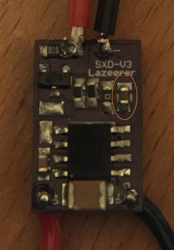
Here’s a pic of the ramp-up capacitor that needs to be removed:

Removing that capacitor means the driver is now instant-on instead of having a one second power-up ramp.

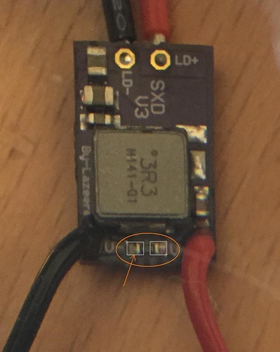
Here’s the resistor to remove to expose the enable pin:

When you desolder the resistor, there are two metal pads exposed (shown here as white rectangles). The resistor is drawing power from the red wire on the right and applying it to the enable pad on the left, meaning the driver is always on. By removing the resistor, you disable the driver until you apply power to the enable pad again. Take the POSITIVE wire from the M1 output of the Orion board, run it through a diode for safety, then through a 10K resistor to limit the power, and attach to the exposed enable pad on the left. Now, when the Orion sends a pulse that would normally drive a motor, it’s turning on the enable pad of the laser driver instead.

You don’t need a super fine tipped soldering iron, just be careful. Heat up both sides of the resistor or capacitor at the same time and use an exacto knife to push it off the pads when it gets hot. Be careful not to get solder on the other parts. It’s a small board, so it’s a little fussy, but it’s doable. The driver itself is relatively cheap, and Jordan from DTR will do this for a small fee, so if you’re not comfortable doing it yourself (or you screw it up) you can always buy one ready to go.


#22

If it makes you feel any better, I blew a $200 diode getting impatient. That stung a little.


#23

Yes impatience can screw things up. Im on a break playing music on the island but had to check. So reading this on my phone, The driver I got is slightly different, from what I can see. But Im sure Ill be up late trying. As usual, your a great help. I guess I should post proto1 and 2 made entirely from scrap old printers and wood. They worked but were slow and not so accurate. One other question… If temporarily I need to revert back to my 1watt diode, I will need to slow the move rate down considerably. Im having forgetful issues concerning the gcodes for feed rates, suggestions appreciated. Also, I fell in love with the apps that will take bmp, svg, etc… and print directly. I have used Inkscape with some laser extensions but apparently turning laser on and off is not generated properly. What are you using for intermediate software?
Thanks again I hope others are learning from my mistakes… I put another nickle in for your help.
Wayne Keller


#24

I use Vectric VCarve because I have a CNC as well, so I started with Cut2D and upgraded a year or so in. I’ve seen people use InkScape to trace images, export to DXF, and then use DXF to GCode. That works but it’s a few more steps.

The companion firmware code for MDraw or BenBox would probably benefit similarly from the changes I made to GCodeParser, I just don’t use those much because I have the tools to make GCode, and you get better control that way. I can set feed rate and laser power for each path independently, then feed them all to the machine at once.

G0 is a rapid move
G1 is a feedrate move, usually followed by F500.0 where 500.0 is mm/min

F, X, Y, and Z are optional params. If left out, the machine just uses the last value for that axis.

G0 X0 Y0 / rapid home
G0 X60.0 / rapid move to current Y, X 60mm
G1 Y50.0 F600 / feed move to current X, Y 50 at 600 mm/min, or 10mm/sec