Trying to understand the Extension Builder's coding concepts


#21

… the ‘treacle’ is still pretty thick but the experiments continue …

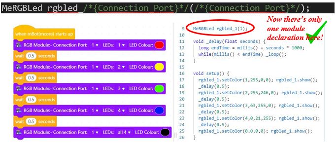
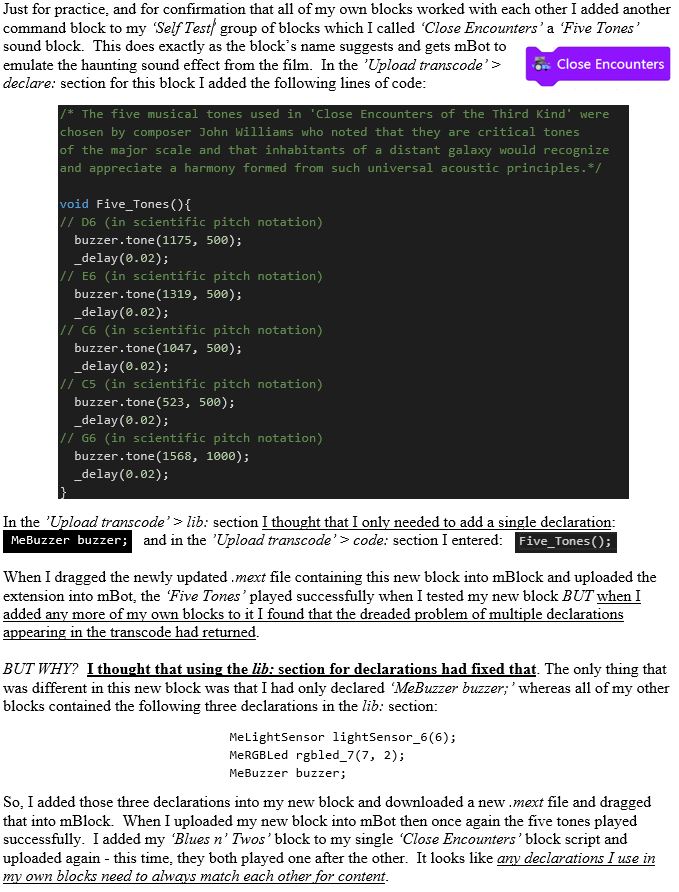
… I have now fixed (sort of) the problem of multiple declarations being added into the transcoding of my own ‘Self Test’ group of blocks; and have no further need for my ‘Initialise mBot’s Devices & My Functions’ block.

It was simple really - in desperation I just tried declaring my devices in the lib: section for each block (leaving just my own functions in the declare: section for each) and it worked. The declaration of devices appeared at the top of the transcode just where it should do and if more than one of my blocks was used then the declaration was not repeated. Hurrah! - BUT if I added a ‘real’ block from the default set then that still caused the double-entry to recur, so this anomaly is yet to be resolved.

Declarations

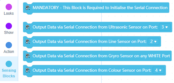
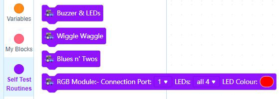
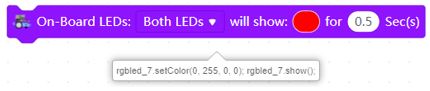
Buoyed up by this, I began work on a final and different block for my ‘Self Test’ group. I wanted to add (for self-learning purposes) both dropdown selection windows and the rather clever ‘bubble’ window that allows you to choose the three values for ‘Color’ Saturation and Brightness’. This feature enables you to adjust the properties of a LED very quickly. This time too, I wanted to create a block that accessed an external module connected to one of mBot’s RJ25 ports. The Me RGB Led V1.0 module that I intended to use has four individual LEDs which can be controlled independently and can be adjusted for both colour and brightness.

NewBlock

There were two important things that I learned here in the creation of this new block. The first was that you need to create Parameter names with a clear & understandable meaning. It is important to note too that when you call that name in your code it will (when you know how) be replaced by the value currently set in your block’s ‘Dropdown’ window.

Secondly I learned about the use of left and right parenthesis markers to configure specific fields (expressions) in the code. When you call any specific parameter name using these enclosing markers it will be replaced in the code by the value currently set in the block for that particular parameter. The Extension Builder software uses the syntax /{parameter_name}/ for this. (N.B. There should be two asterisk symbols here, but this editor is stripping them out. Each one is between the forward slash symbol and the curly brace symbol).

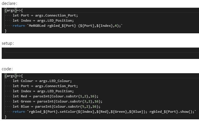
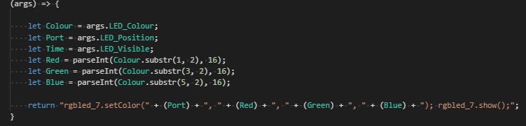
Once I had the two ‘Dropdown’ parameters working I had a new problem to solve with the final parameter - the ‘bubble’ window. If the on-board LEDs on mCore are being programmed using the ‘Color’ option then this returns RGB values that can be used in the format MeRGBLed rgbled _portnumber (0, Red, Green, Blue); etc. But, if the external Me RGB Led module is being programmed instead then, for some reason, the ‘Color’ option returns the hexadecimal value of the colour chosen; so the default setting of RED returns #ff0000 and NOT values in the format of 255,0,0.

Trying to use this hex value output seems to be virtually impossible to achieve using Arduino C coding and any code containing such a values immediately crashed on upload indicating that there was a “stray ‘#’ in program”; the leading hash symbol (#) was not acceptable. The only way that I could solve this problem was to use some JavaScript code instead - something that was / is totally new to me.

This next image shows the ‘Upload transcode’ windows for my new block. Note the use of clear Paramater names here:

Progress has defilitely been made and I now have over forty pages of comprehensively explanatory notes on what mBlock’s ‘Extension Builder’ actually does and the best way to start using it successfully. - Watch this space!


#22

Good for you! I’m glad to see you’re figuring stuff out!


#23

Hi everyone

My last experiment (shown in the previous post) still showed me using the declare: section.

Since I still had exactly the same problem of multiple declarations being added by my blocks, I tried two alternative ways of declaring the Me RGB Led module. Firstly, I tested by using left and right parenthesis markers to declare my parameter names in the lib: section knowing that these names would be replaced by each of those values currently set in the block for the parameters declared.

e.g. MeRGBLed rgbled_/{Connection_Port}/(/{Connection_Port}/,/{LED_Position}/, 4);

Secondly, I tested the alternative JS method of declaring the module in the form of :

(args)=>{
let Port = args.Connection_Port;
let Index = args.LED_Position;
return MeRGBLed rgbled_${Port} (${Port},${Index},4);
}

Finally, I tried declaring my parameter names in the lib: section once more - but this time removing the ‘Led_Position’ (index) value (see below):

Much%20Better%20Code

This did solve the dual entry problem caused by using multiple blocks and in response to the block code sequence shown above, all four individual LEDs on the external module dutifully lit up in turn.


#24

Congrats! :grinning:


#25

Hi Everyone - Here we go again - A new block recreates the old ‘multiple declarations’ error:


But as usual there was a solution.


#26

Glad to here that!


#27

I have now added-to and tidied up my extension blocks into two groups (see below).

In ‘Upload’ mode they work well. So far, I had only tested my extension blocks in ‘Upload’ mode so I switched mBlock into ‘Live’ mode, updated the firmware and reconnected mBot. A quick test with one of mBlock’s default blocks (the ‘shows color’ block) demonstrated that clicking a block in the scripts window would immediately action a response on mBot’s mCore board (in this case, the LEDs illuminated).

Here I attempted to emulate the Arduino C code required to turn mBot’s LEDs on by setting the code in the ‘When block is running (onRun), execute:’ window to generate the complete command sequence shown below:

Live%20output

But all I got here was my code line returned as output in a speech bubble. In ‘Upload’ mode transcode, this line would have worked, but this is clearly not the way to do it in ‘Live’ mode using JavaScript - Hmm! - So how do I do this in JavaScript? - Any ideas anybody?


#28

Nice progress! w3schools has a JavaScript tutorial that might help.

~Best_codes


#29

Being a complete Javascript newbie, I am already refering to the excellent w3schools for syntax but it doesn’t really help with the specialist quirks and foibles of the Extension Builder software. Someone on the Forum somewhere must have made an extension block do something in ‘Live’ mode. @tech_support ? @ralcoberro ? @Crackel ?


#30

For those following my progress in this lengthy post, my test set of extension blocks has now been published - THANK YOU Makeblock!

mBot users can now download and test these (‘Upload’ mode only) if they wish.

Enjoy! - & meanwhile I’m back to my ‘Live’ mode experiments.


#31

I love it, I wanted to do like you but I don’t have much time… I’ll try to go and try this extension :wink:


#32

That’s awesome! :smiley: I’m so glad for you! I’ll try it now.


#33

Reluctantly (and after useful feedback from like-minded Forum members) I came to the same conclusion that they had - Makeblock have not made it possible to code your own extension blocks to enable them to work in ‘Live’ mode.

So, I have moved on from what was a dead-end line of investigation to creating a new Extension - not just for mBot but for all ‘old-style’ Makeblock mainboards (Orion, mCore, Auriga & MegaPi) and the blocks that I am creating here can transmit real-time data from commonly used Makeblock sensors to show feedback output on the mBlock ‘Stage’ display.

new%20extension%20blocks

These blocks have to work in ‘Upload’ mode and therefore require the use of the ‘Upload Mode Broadcast’ extension which is commonly available for these devices in the mBlock ‘Extension Centre’. So far though, these blocks work OK (but with some limitations on what you can do with the output).

The two ‘Output Data’ blocks do all the work of getting the value of each sensor and then broadcasting the value to a receiving script on the Sprites ‘Stage’.


#34

I should have mentioned in the post above that the ‘Upload Mode Broadcast’ extension must also be added into the blocks palette of the Sprites tab. But this only has to be done once, since if a mBlock file is saved then the extension remains with the file and will be seen again in the Sprites blocks palette whenever the file is re-opened - has anyone any idea why adding this extension also, for some strange reason, activates the ‘Teachable Machine’ extension too? The Devices tab extension (equally strangely) does NOT however remain in the file when saved and it must be added every time to an extension like this (which requires its use to work) whenever it is opened.

The blocks shown above do work OK and do report back output from the ‘standard issue’ ultrasonic and line sensors; but only when tethered (connected by a serial USB cable) - they do not work when connected wirelessly using theBluetooth Serial dongle. The ‘Stage’ output is returned in variable monitor read-out windows (but only if the variable is ‘ticked’ in the blocks palette) and the useful and unclutterd ’large’ (but orange) output read-out is the best one to use here. N.B. Monitor read-out windows take on the colour of the block generating the output and ‘Variables’ blocks are orange.

However, I wanted to use in ‘Upload’ mode the same methods that I had used before in ‘Live’ mode to create output screens that could display feedback values of any size or colour.

Blocks%20method

In mBlock I created blocks that could break up a returned variable containing sensor output into individual hundreds, tens and units values which could then be used to choose a matching sprite costume - so simple to do when you know how. For more guidance on this, its in my original book ‘mBot & Me vol I’ - you can download this (free) via the following link:

https://education.makeblock.com/resources/res-mbot/56549/

The blocks shown above can be transcoded and used in extension block transcode (Arduino C):

Arduino%20C%20method

In my experiments with Broadcast messages which could send data from the ultrasonic sensor back to the stage in ‘Upload’ mode I eventually realised that the values shown for each digit returned were always in the region of 49, 55, 56 etc. and after much fiddling with the Arduino C code lines and many repeated uploads I worked out - eventually that these values were being returned in ASCII Decimal format e.g. 0 (zero) was being returned as a value of 48. Once I had established this fact then I simply used the method (sensor_value _returned - 48) to fix the problem with each line of code.

Stage%20output

Now, the ‘Stage’ display had individual digits to use and at last I could produce real-ime graphic output such as that shown above. The work goes on with the adding of more individual sensor blocks to this extension and I will publish it eventually…


#35

Any more progress?


#36

Yes progress is being made - I’ve just been waiting for the Forum to return to normal loading speed again.
I have now added two more extension blocks to my Upload mode experiments. In addition to the Ultrasonic and Line Following sensors I have now added a block for reading the Me Colour Sensor and the Me Gyro sensor. This last block works OK but not as good as the extension created by @Dr.K (Dr. “Kilo” Watt).

Sensing%20Blocks

I have been experimenting (as you can see in the image below) by extracting data from these extension blocks and displaying graphical feedback updated in real-time on the mBlock ‘Stage’ without having to resort to the standard, and somewhat limiting mBlock ‘variable monitors‘.

If you want to know how to create output feedback screens like this, there is some guidance in my original book ‘mBot & Me vol I’ - you can download this (free) via the following link:

https://education.makeblock.com/resources/res-mbot/56549/

I have also been looking in some detail at using feedback from the Me Gyroscope module and despite guidelines to be found elsewhere …

… (see MeGyro Module: General Introduction to Gyros) …

… I have had to modify what is commonly described (and frequently repeated) as the correct mounting procedure. To test my gyro module I built a simple ‘wind-vane’ construction with the module attached to the top of it and mounted it on a small tripod with a swivel/ tilt unit (see the image below):

Using this simple rig clearly demonstrated that the X axis arrow printed on the module needs to point across the width of a robotic device and not forwards along the length to enable feedback to correctly indicate the sideways ROLL attitude as X values. The Y axis arrow on the module therefore needs to point along the length (the longitudinal axis) and towards the front of any robotic device to correctly indicate the up/down inclination PITCH attitude as Y values. This leaves the Z-axis pointing vertically through (up or down) and returns the DIRECTIONAL HEADING of the module (the YAW attitude) as Z values. The Gyro module, as you can see above (and contrary to expectations) should be mounted upside down with the Z-axis pointing downwards which will then output POSITIVE values for the first 180° of CLOCKWISE rotation of the robotic device.

N.B. For the remaining 180˚ of the Z axis rotation minus (negative) values are returned; and a calculation is required to make sure that only positive values are interpreted from the sensor readings:

If Gyro_Z>0 and <180
 	Then Gyro_Z Modified = Gyro_Z
Else
If Gyro_Z <0
 	Then Gyro_Z Modified = (Abs (Gyro_Z-180) +180)

So, onwards and upwards …


#37

Have any of you ever seen mBlock 5’s ‘white screen of death’? Crashing this usually very stable piece of software is almost unheard of but can be caused it seems by having too many project assets.

In the creation of the ‘stage’ feedback screen (which you can see in my previous post), I needed to make costumes for the Z axis (the directional heading) of the Gyro; 360 of them in fact and that is a lot of costumes to duplicate and edit - so many (and such a tedious a task) that I had to do them in batches over quite a few days.

heading

Once I had duplicated 200-or-so entries, the Costume Editor became noticeably sluggish. By the time that I passed 350 costumes, my first software crash happened; and whilst I could restart and run mBlock with my project functioning normally, as soon as I entered the Costume Editor screen it crashed again. Whilst trying to find my way around this problem, as a test I found that I could make a new sprite in the same project and duplicate costumes quite happily; but the many costumed Gyro sprite always crashed on opening it in the Editor!

I removed (by exporting it) my ‘Gyro_Z ‘ sprite from my project and reloaded the resultant .sprite3 file (270Kb in size) into a new project with no other assets present and then the resultant .mblock file became approx. 430Kb in size. It should be mentioned here that my sprite also contained the matching decision-making (if/then) block scripts needed to interpret module feedback into costume output. Sadly, this new project file also crashed mBlock as soon as I opened the Costume Editor - so what was I to do? …

… As a last resort, I tried opening this new single sprite project in the online mBlock Web version of the software (I always use the Desktop PC version). Amazingly the Costume Editor ran much more smoothly and it was now possible to create more costumes, and these were quicker to implement by copying rather than duplicating) and I could now complete my total of 360 costumes with ease; including their accompanying block scripts - which for ease of visibility (and duplication) I broke into vertical runs of 22 if/then decisions under 16 ‘My Blocks’ headings (see part of the first three of these below).

I loaded (imported) my newly completed ‘Gyro_Z ‘ sprite back into my original project where it worked perfectly giving me 0º to 360º Headings for the Gyro feedback screen. All that I had to do now was not to open this sprite in the Costume Editor.


Color sensor isn't working
#38

I like making my mBlock prjects that don’t use devicees on turbwarp.org. It normally doesn’t crash.


#39

Has anyone got the Me Color Sensor module to return accurate RGB Values?

The predefined colour values returning (2 for RED etc.) work well but the method shown below for returning individual RGB colours.using colorSensor.ColorDataRead(); does not work nor do similar colorSensor library calls: ReturnColorCode(); ReturnColorData(); or ReturnRedData(); etc.

Red should return 255,0,0 in RGB but the sensor using ColorDataRead(); returns 55,7,4
Green should return 0.255,0 in RGB but the sensor using ColorDataRead(); returns 12,27,7
Blue should return 0,0,255 in RGB but the sensor using ColorDataRead(); returns 62,66,58

Any ideas?

COLOUR is the name (replacing ‘colorSensor’) that I have given to my Colour Sensor Object and the Upload transcode that I am using in my Colour Sensor extension block is shown below: -

uint8_t detectedColor(MeColorSensor COLOUR, uint8_t colorType){
if(colorType == COLOUR.Returnresult()){
return 1;}
return 0;
}
uint16_t getSingleColorValue(MeColorSensor COLOUR, uint8_t colorType){
long rgbcode = 0;
COLOUR.ColorDataRead();
if(colorType < 3){
rgbcode = COLOUR.ReturnColorCode();
Value_Colour = COLOUR.ReturnColorCode();
switch(colorType){
case 0: return (uint8_t)(rgbcode>>16);
case 1: return (uint8_t)(rgbcode>>8);
case 2: return (uint8_t)rgbcode;
default: return 0;}
}else if(colorType == 3){
return COLOUR.ReturnGrayscale();
Value_Colour = COLOUR.ReturnGrayscale();
}else{
return 0;}
}
void Control_Light(MeColorSensor COLOUR, uint8_t lightState){
if(lightState == 0){
COLOUR_/{RJ25_Port}/.TurnOffLight();
}else{
COLOUR_/{RJ25_Port}/.TurnOnLight();
}
}
void Colour_Sensor_On(){
COLOUR_/{RJ25_Port}/.SensorInit();
Control_Light(COLOUR_/{RJ25_Port}/, 1);
}
void Colour_Sensor_Off(){
Control_Light(COLOUR_/{RJ25_Port}/, 0);
}

void Get_Colour_Value(){ // PROBLEM WITH RETURNED RGB VALUES HERE
Colour_Sensor_On();
while(1) {
**Value_Red = getSingleColorValue(COLOUR/{RJ25_Port}/, 0); _
_
Send_Colour();_
_
Value_Green = getSingleColorValue(COLOUR_/{RJ25_Port}/, 1);_
_
Send_Colour();_
_
Value_Blue = getSingleColorValue(COLOUR_/{RJ25_Port}/, 2);**_
Send_Colour();
if(detectedColor(COLOUR_/{RJ25_Port}/, 0)){
Value_Colour = 0; // Pre-Defined White
Send_Colour();}
if(detectedColor(COLOUR_/{RJ25_Port}/, 2)){
Value_Colour = 2; // Pre-Defined Red
Send_Colour();}
if(detectedColor(COLOUR_/{RJ25_Port}/, 4)){
Value_Colour = 4; // Pre-Defined Yellow
Send_Colour();}
if(detectedColor(COLOUR_/{RJ25_Port}/, 5)){
Value_Colour = 5; // Pre-Defined Green
Send_Colour();}
if(detectedColor(COLOUR_/{RJ25_Port}/, 7)){
Value_Colour = 7; // Pre-Defined Blue
Send_Colour();}
if(detectedColor(COLOUR_/{RJ25_Port}/, 9)){
Value_Colour = 9; // Pre-Defined Black
Send_Colour();}
}
}
void Poll_Colour(){
broadcaster.on(String(“Poll_Colour”),Get_Colour_Value); // on receipt of message get sensor value
}
void Send_Colour(){
broadcaster.broadcast(String(“Colour_Value”),String(Value_Colour));
broadcaster.broadcast(String(“Red_Value”),String(Value_Red));
broadcaster.broadcast(String(“Green_Value”),String(Value_Green));
broadcaster.broadcast(String(“Blue_Value”),String(Value_Blue));
broadcaster.broadcast(String(“Update_Colour”)); //return sensor values via these individual messages
broadcaster.callOK();
}


#40

Hmm… :confused: