ellfire,
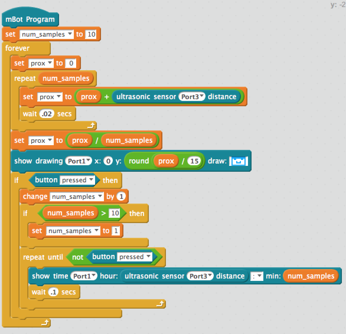
Here is a copy of the code so far. I have made some changes to the pin configuration (for use with my current hardware setup). I have also made several changes to the program flow. I have tried to include as many comments as I thought necessary.
I’m not quite clear on how you want to fading/transitioning from green to red. If you could make a graph or attach a photo of how it should work, I’ll see if I can help some more.
Mike
#include <Makeblock.h>
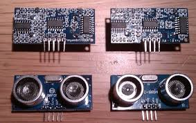
#include <NewPing.h> //Library for improved ultrasonic sensor readings
#include <SoftwareSerial.h>
#include <Wire.h>
//Declared Global Constants
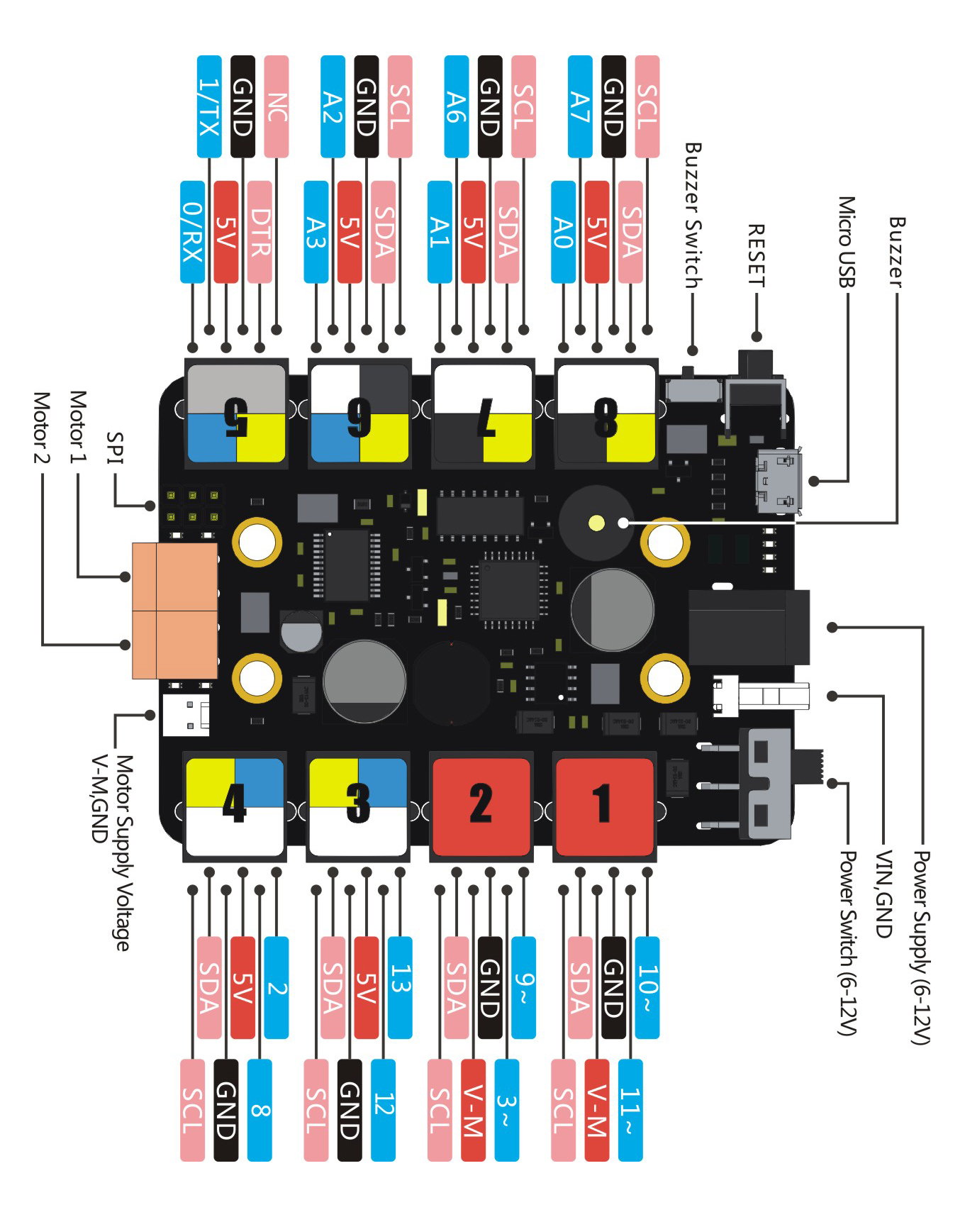
#define TRIGGER_PIN 15 // *** this was changed *** Set to pin 13 when using PORT_3 for Ultrasonic Sensor
#define ECHO_PIN 15 // *** this was changed *** Set to same pin as trigger pin.
#define MAX_DISTANCE 200 // *** this was changed *** Maximum distance we want to ping for (in centimeters). Maximum sensor distance is rated at 400-500cm.
#define MAX_BRITE 50 // *** this was added ***
#define TRANSISITION 15 // *** this was added ***
//End Declared Global Constants
MeUltrasonicSensor ultraSensor(PORT_8); //*** this was changed *** Ultrasonic module can ONLY be connected to port 3, 4, 6, 7, 8 of base shield.
MeRGBLed led(PORT_3); //Set port location for LED module
Me7SegmentDisplay disp(PORT_4); //Set port location for 7 segment display
NewPing sonar(TRIGGER_PIN, ECHO_PIN, MAX_DISTANCE); // NewPing setup of pins and maximum distance.
//Declared Global Variables
int rBrite = 0;
int gBrite = 0;
//End Declared Global Variables
void setup()
{
Serial.begin(115200); // Open serial monitor at 115200 baud to see ping results.
}
void loop() // Put your main code here
{
int dispDist;
int cmPing = sonar.ping_cm(); // each time you ping, you get a new reading
delay(50); // Wait 50ms between pings (about 20 pings/sec). 29ms should be the shortest delay between pings.
if(cmPing > 0){ // this will drop zero values, which seems to be the cause of most of the jitteriness
rBrite = 0; // reset
gBrite = 0; //reset
if(cmPing <= TRANSISITION) { //Sets value of the red LED from 0 to 55 based on distance
rBrite = map(cmPing, 0, TRANSISITION, MAX_BRITE, 0); // https://www.arduino.cc/en/Reference/Map
} else {
gBrite = map(cmPing, TRANSISITION, MAX_DISTANCE, 1, MAX_BRITE);
};
dispDist = cmPing; //Create an integer variable to let 7 segment display show value of sonar.ping
Serial.print("Distance : ");
Serial.print(cmPing);
Serial.print(" cm, ");
Serial.print("rBrite : ");
Serial.print(rBrite);
Serial.print(", gBrite : ");
Serial.println(gBrite);
};
disp.display(dispDist);
for(int i = 0; i <= 3; i++){
led.setColorAt(i, rBrite, gBrite, 0); //LED i R G B
}
// led.setColorAt(1, rBrite, gBrite, 0); //LED 2 R G B
// led.setColorAt(2, rBrite, gBrite, 0); //LED 3 R G B
// led.setColorAt(3, rBrite, gBrite, 0); //LED 4 R G B
led.show();