First of all let me thank you all.
Then my first question.
I’d like to control the mbot with the Arrow Keys of my notebook/pc.
AFter a bit of search I know this is possible.
But the question is:
Does it only work for the bluethoot version or for the 2.4 G version as well?
Control mBot using arrow keys - does it work for 2.4 G version?
dutes
#1
mBlock5 NO WIRELESS MODE for 2.4G mBot
PinkyPepper
#2
Hi,
it works for the 2.4 GHz version as well if you’re using mBlock. No problem. Just be sure to use two brown coding blocks for every arrow key, the “When key pressed” block and “When key released” block so the motor will be turned of when you don’t press any arrow keys anymore.
Good luck!
Greetings, PinkyPepper (https://www.youtube.com/channel/UCtVRNnOm-70dMkJt9vUSGWA)
daveh
#4
My notes for using the 2.4G USB controller for Ultimate 2.0:
Method to Control MakeBlock Ultimate 2.0 robot with “2.4G Wireless Controller” USB Stick
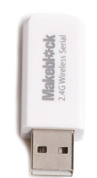
“USB stick” - the 2.4G Wireless Controller
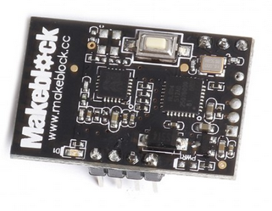
“Module” - the 2.4G Wireless Serial board
- Start mBlock software (PC version in this example)
- With battery power off, connect the USB cable PC to MegaPi
- Start mBlock software, select menu items:
a) Boards>Ultimate 2.0(MegaPi)
b) Connect>Serial Port>COM4 (check your PC’s COM port number in Device Manager)
c) Extensions>Makeblock (to enable software) - Update firmware
a) Connect>Upgrade Firmware
b) confirm that upload completes (“Upload Finish” will be displayed) in dialog box
c) close dialog box - Disconnect the USB cable
- Connect battery power to MegaPi
- Turn on MegaPi
- Press the white “pairing” button on the Module
a) blue LED will flash rapidly - Insert USB stick into PC
a) blue LED will be solid blue - Enable USB stick communication
a) Connect>2.4G Serial>Connect - Program robot
a) Open mBlock software
b) Enter the below program into mBlock software:
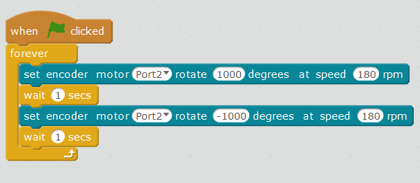
- Click the green flag to run the program

dutes
#5
Thank you Daveh. Supereffective.
Just to understand it better:
Your Step-by-Step procedure is about adding a 2.4G Wireless module to a bluethoot-only version, right?
If I have already a 2.4 G Wireless version of mbot, will I need that procedure?
Can you, please, tell me what the point n.11 is for?
Many many thanks. 
daveh
#6
The steps I outlined are for a "“2.4G Wireless Controller” (which is pictured above, the white “USB Stick”) when paring to the Ultimate 2.0 robot (although the procedure should be similar for mBot).
I found this particular 2.4G Wireless Controller to be kind of quirky, which is why I made those notes (for my own reference).
The 2.4G Wireless Controller makes a live Bluetooth connection from your PC to the robot, allowing for “control by arrow keys” which was the original question.
#11 in the steps allows for confirmation that the connectivity between the PC and the robot is active, and it just a basic test to run the motors.
From that point, I begin to adapt the SCRATCH code for the project I’m working on. The example below is for the Ultimate2.0 robot, the build is “Camera Dolly”, and I programmed the robot to move under keyboard control:
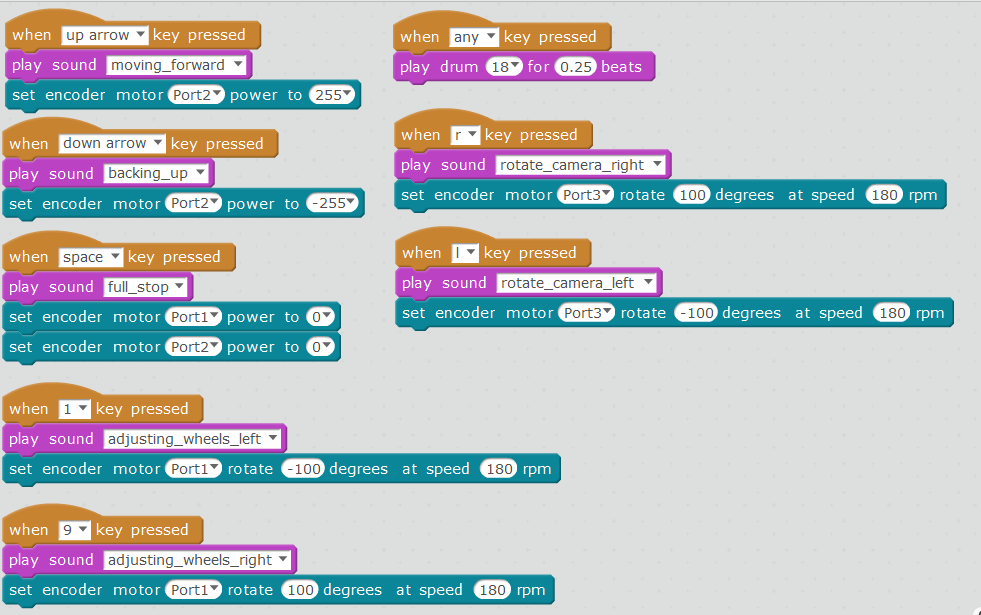
I used various settings for motor speed/rotation etc depending on the way I wanted to robot to act after a key press.
I usually watch the robot while I’m driving it, so I added the “play sounds” step (in purple) for instant feedback (the robot response is a bit slow).
More steps are:
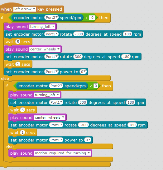
In this case, I decided that the “turn left” command needed some additional programming. If the robot is not moving forward, then turning the wheels to the left did not result in an actual turn. So I used a conditional (if statement) to check the speed of the robot.
In addition, once the wheel is turned to the left, the robot makes a slow left turn, so I decided to automatically “recenter the wheels” at the “end” of the turn. That way, when pressing the “left arrow” button, the robot will make a nice left turn, then continue straight (until told to stop).
The code “set encoder motor Port 1 power to 0” is used because I noticed that there is still a small amount of power being sent to the motor (not enough to rotate the wheel, but you can hear it “whine”).
The turning is usable for forward or reverse.
And if the robot is not turning, then my PC plays the sound “motion require for turning”.
Here’s the last set, for a right turn:
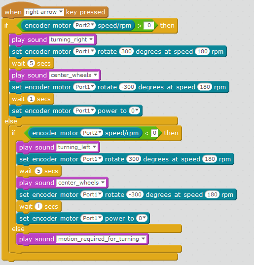
All of this extra coding is just me having fun with the robot. There are a lot of different ways to build this project, but I though this way was a lot of fun.

dutes
#7
Amazing Daveh. Hope you keep going. This is pure passion for what you do. And thank for your kind availability. Best regards