Connecting Me 130 DC motor (12v) to mbot


#1

Hi all,

I just bought the “Me 130 DC motor” (fan module) and RJ25 adaptor for my mbot. I now know there are two types of fan modules. One fan module (5v) has an RJ25 cable connection and the other (12v) has an orange 2 pin connector for Orion board.

Has anyone successfully connected the 12v fan module to mbot? Will the 12v fan spin with lower mbot voltage? I plan to replace the orange 2 pin connector with a 3 pin 2510 connector (obviously only 2 pins will be used) and then plug it into the RJ25 adaptor.

Returning the fan is not an option.

Cheers
Carlos


#2

The 12v motor will spin very slow at 6v.

I see on the specs for mbot it is designed to run on voltage from 3.7v to 6v. I make an assumption that the 6v limit is because of the motors that come with mbot can only run 6v but if your not going to be using the standard motors and be using 12v motors it might be possible to run the mbot from a 12v source like the mbot ranger.

see the cut from below schematics from https://www.makeblock.com/project/mcore that show the voltage to the rest of the board is regulate down to 5v from higher inputs.

I would ask tech support.


#3

Hi Shane,
Thanks for your very helpful explanation. It makes perfect sense. That is what I thought/ hoped might happen given my limited (i.e. non existent) electronics knowledge. A slow running fan is fine. I just wanted my son to see some movement and action to keep him interested.
Cheers Carlos


#4

Further to the above. I’m currently running my mbot on 4 x 1.5vAA batteries. 6V total. I realise 12V fan will run slower on 6V. I was about to buy a 3.7V rechargeable battery but now not sure I should. Appreciate any thoughts.

Carlos


#5

Hi
You can buy this one.


Makeblock


#6

Thanks Tech_support however that doesn’t answer my question.

Will there be a difference in performance between the two battery options - 4 x 1.5V AA batteries vs 3.7V Lipo rechargeable. And specifically what impact will these two batteries have on the aforementioned plan to connect a 12V DC motor.

I have read other forum posts that mention different performance between 3.7V vs 4x1.5AA in running motors. May seem obvious 3.7V compared to 6V. Just wondering if there is something else I haven’t realized.

Thanks


#7

The schematics are not the best labeled and easiest to read.

As in many PCB designs there can be multiple different voltages. The Mcore seems to have 4 labled VBAT, VBUS and V-M and 5v. VBUS is the voltage in from the USB lead, VBAT is the voltage in battery, V-M is the voltage that is connected to the motors and seems to be just connected to VBAT on this board then 5v is regulated from either VBAT or VBUS. The voltage regulator is labeled so I can’t check the specs on it to see what is max and min voltges it can take as inputs to still be able to regulate to 5v. Most of the circuits are running off the regulated 5v.

The main thing for you is that the motors are powered by V-M which seem to be connected to VBAT (battery input) so will only receive what ever voltage battery is connected.

It would be nice if Tech_support was able to shed more light on exactly what their product is capable of handling and the do and don’t and what will produce best results


#8

The 3.7v will turn the 12V motor very slowly, if it turns it at all (should do since there’s very little load). Don’t see why you’d want to go that low in voltage though.

@OutoftheBOTS - the spec sheet for the mCore gives a voltage range of 3.7V to 6V. http://learn.makeblock.com/en/mcore/


#9

It is nice to be able to check out the components that are used on the PCB to get an idea of the specs. To get an idea the Auriga schematic does label the voltage regulator used and we can google the specs of it. You can see on the datasheet from the manufacture that it can handle inputs up to 28v with max current of 3amp. I also the the H-bridge that drives the motros is a TB6612FNG and it can handle up to 15v.

The specs for Auriga from makeblock says 6v to 12v.

If I am using motors that cann handle 15v then I should be able to run the Auriga on 15v and if I am not using and motors then I should be able to run the board up to 28v.

Specs for the TPS54331 voltage regular on the Auriga http://www.ti.com/lit/ds/symlink/tps54331.pdf
Specs for the TB6612FNG https://www.sparkfun.com/datasheets/Robotics/TB6612FNG.pdf

Capture2


#10

Sure. The TP3605 on the mCore looks like it will handle up to 28v at 2amps.

Prof_montoya is talking about plugging the motor into the RJ25 which is 5V only, not P2 and P3 from the DC driver, which I’m guessing he’s using to drive wheels on the MBot.


#11

OK yes I just scrolled up and read that. I certainly wouldn’t recommend doing that as you would be attempting to drive the motor from the MCU not a H-Bridge.

You shouldn’t drive anything directly from an MCU GPIO pin but rather use the GPIO pin to operate a switch to turn a power supply on/off, this is what a H-Bridge does (TB6612FNG)

Although I see people drive a small LED directly from a MCU due to it needing such little power it is better to use a transistor.

Motors or relays are about the worse thing you can connect directly to a MCU because of the back EMF. Anything a magnetic field collapses it generates a back EMF. Motors and relay do this a lot.

To connect that motor to a RJ25 port he will at least need this https://www.makeblock.com/project/me-dual-motor-driver but even then he will only get 5v not V-M like the orange ports and further more the motor will still create electrical noise on that 5v line that the MCU my not like. I would recommend attaching it to a red labled port as they not connect to the 5v line but rather the V-M line


#12

Very good points, well made.


#13

Hi all. Thanks for the very detailed responses. A lot of it went straight over my head so I did the only thing I could think of… I wired it up and hoped for the best.

I connected the black wire to GND and white wire to VCC on slot 1 of RJ25 adapter, and switched it on.

It worked!! Infact the fan turned at great speed. The only problem was the fan was working and I had not written any code. At least I know fan works.


#14

Here is a photo


#15

VCC is 5V , so yes, the fan will switch on, no code required :slightly_smiling_face: and the fan will draw as much power as the batteries can supply.

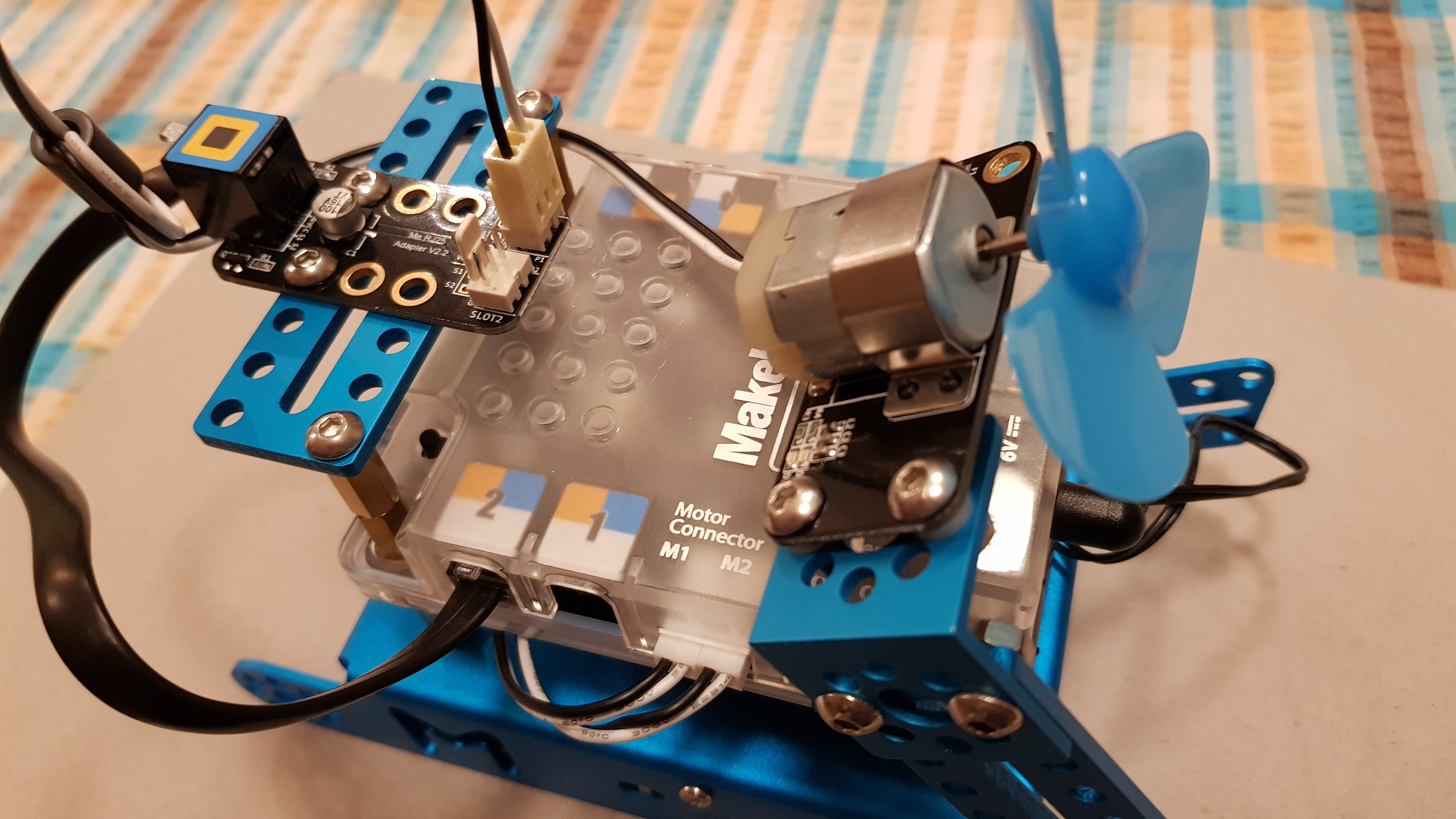
in order to control the fan however, you’ll need to use logic pins to switch the power on and off to the fan and the way you do that is by using a motor driver (or simply a transistor)

What OutOfTheBots said was right - if you try to supply the fan with power from S1 or S2 (the signals from the pins connected to the RJ25), you risk damaging the processor. He mentioned Back EMF - When a motor rotates in the reverse direction, stops or slows down abruptly, a current flow back to the motor’s power supply (the digital pin of the processor in this case), this in essence kill the pin completely. Always, always, always, protect your CPU!

The pins of the CPU are not designed to supply current to drive motors, they’re designed for logic, not power.

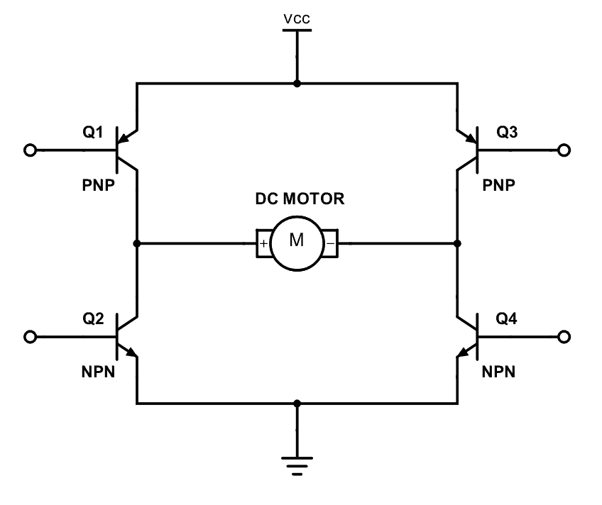
When hooking up motors to a you need to use a transistor or H-bridge which allows you to use the digital pin as an on-off switch. (an H bridge is an electronic circuit that can drive the motor in both directions - it’s called an H bridge because it is basically just four transistors, and the circuit looks like the letter H).

The function of a transistor is to permit the current to flow from VCC to ground, through the motor when a digital pin is high (5v), or stop current flowing when a digital pin is low (0v)

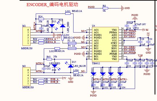
https://www.makeblock.com/project/me-dual-motor-driver <- this is a proper motor driver. (you’ll see from the description it has an H bridge).

Have a look here: http://www.thebox.myzen.co.uk/Workshop/Motors_1.html for more information

We’re just trying to make sure you don’t make any expensive mistakes, and it’s always worth learning a little bit about the electronics as you go :slight_smile:


#16

At the risk of confusing you further, this is what an H bridge looks like.
Q1, Q2, Q3 and Q4 are transistors, and at their simplest, act like switches.
So to turn the motor in one direction, you’d switch on Q1 and Q4
To turn the motor in the other direction, you’d switch on Q3 and Q2.
The pins with the circles do the switching on and off (they’d be connected to your processor pins)

For a proper description of what it does, take a look over here: https://www.build-electronic-circuits.com/h-bridge/


#17

I would be very cautious of connecting the motor directly to the VCC pins as well. The VCC is also the line that supplies the processor with power. Motors give off a lot of EMF and you greatly risk damaging the sentive electronics at the very least you should have a fly back diode.


#18

Hi. Thanks for the advice. I didnt realize “The pins of the CPU are not designed to supply current to drive motors, they’re designed for logic, not power.” I will do some more research.

PS. I have an mCore (mbot) which doesn’t connect to the dual motor driver component (red color sticker). At the risk of sounding even more of a noob, what if i connect the fan directly to one of the onboard motor drivers.


#19

Looking at the schematic here https://www.makeblock.com/project/mcore the motor ports are driven by a H-bridge so will provide EMF protection from the motors and will provide the switching for the MCU to be able to turn the morot on/off and forwards and backwards :slight_smile:


#20

Ah yes, silly me, I’m not used to the MCore. As OotB says, the on-board motor drivers can definitely drive a fan, simply wire up each of the pins on one connector to each side of the fan. You should then be able to drive the fan using the “Move forward at power x for y secs” block (or turn left or right depending on which motor pins you’re using).