I boughtthis rechargeable NiMH battery and connected it to my MeOrion board. I had two DC motors connected to M1 an M2, and they worked initially, but when I increased to full power (255), they stopped. Now the motor ports on the board do not work. The motors work on another MeOrion board, so it’s not the motors.
Did I burn out something on the MeOrion? Was it because I was running the motors at full power?
Is it generally unadvised to set the motor speed to 255?
9.6 V NiMH battery pack burned out motorport on MeOrion
rvondrak
#1
tech_support
#2
Hi rvondrak,
Could you take a clear picture for the front side of the issue Orion board?
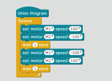
Also, to double check if the driver chip on the Orion board faulty or not, please upload this program to the Orion board and check if there are green led and yellow led besides each motor port alternating lit up.

Besides, may I know when and where did you buy this Orion board? Could you send its receipt to email address daisy@makeblock.com?
rvondrak
#3
There are no LED lighting up around the motor ports. I also checked M1 and M2 with a multimeter and there is no voltage.
I bought the starter robot kit from Radio shack a couple years ago. I might be able to find a receipt if I looked hard enough.
It’s my guess that when I tried running the motors at full power, they drew too much current and burned the board out. Before using the rechargeable battery pack, I used 6 AA batteries. I also had a bluetooth communication device connected to control the robot wirelessly. When I would turn the motors on full power, they bluetooth would lose connection. I assumed it was because the motors drew too much power and the bluetooth temporarily lost power. I figured a better battery pack would be able to supply the needed power for the bluetooth and the motors. This is what leads me to thinking the full motor power burned out the board.


That’s really strange because the motor ports (1-2) are supposed to support 6-12VDC and 9.6 should have been well within tolerance.
rvondrak
#6
I don’t think it’s the voltage that’s the problem, I think it’s the current they pulled.
The motors did work at lower power, but it was when I put it to full power that they slowed and stopped. I plugged in an external motor driver to Ports 1 & 2, and when running the sample code above (which only goes to run speed 100), it seemed to work.
I hear you, but it’s still odd that they were able to draw more that 3 amps. Were those the stock motors?
Well, the motors themselves seem to draw < 1 amp (link) but the Orion board (link) itself has a max of 3 amps input. I glanced at the schematic and didn’t see anything that looked like a buck converter, but I didn’t dive in too deep on that (would be more of a question for @tech_support).
tech_support
#10
Hi rvondrak,
Our engineer has an analyze on this issue. Normally, the orion board has an overcurrent protection function. For normal use with 9.6v supply won’t burn the driver chip.
While, if there was motor stall (in usually usage, try best to avoid the situation that there is external force on the motor to prevent it from rotating when it rotate), it can generate relatively large currents and heat to cause a short circuit for the driver chip. Since you have the multimeter, you can also test the resistance for the M1+/M1- or M2+/M2- , if it is short circuit, the driver must been burned.
The driver chip model is TB6612FNG/TOSHIBA, if you have the electric iron, you may the driver chip from local shop and solder it to fix the board.
rvondrak
#11
The motors were only driving the wheels, so there was very little external force applied; the motors weren’t stalled.
When I check the resistance of M1+/-, how much resistance should there be?
I do have a soldering iron, but I don’t think I have the skill to replace the driver chip.
rvondrak
#13
I did some tests on a new orion board. I measured the voltage and amperage under different motor speeds.
Motor power 100; 2.5V; 0.115A
Motor power 200; 5V; 0.16A
I got the same values when I used the 6 AA batteries as when using the 9.6 V battery pack. I was only testing one motor and not two, so maybe the load on the chip increases with two motors running. I also didn’t have wheels on it.
One thing I did notice is that when I first started the motors up, or reversed direction, it increased the amperage to over 1 amp momentarily. This makes sense because of the torque needed to start or reverse. So maybe with two motors going full power and with wheels attached, it drew enough current to burn the motor driver chip.
I don’t want to burn another orion board trying to test the max speed. I’m just going to cap the motor speeds at 200.
tech_support
#14
Hi rvondrak
You did test a lot, when the motor reverse the direction, it will produce a relatively large back-EMF voltage.
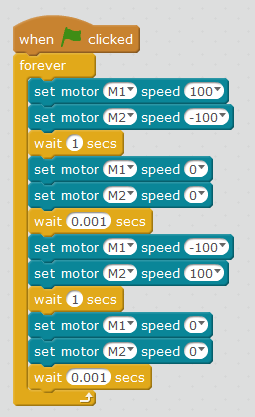
Actually, my test program provided in previous reply is not a good example, when we want to reverse the direction of the motor, it is better to slow its speed to 0 with millisecond, then reverse the direction. Like the example program below, in this way, it can decrease the back-EMF voltage and protect the driver chip.