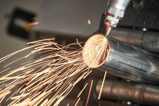
Drawing a layout for laser pipe cutting can be done using various software applications designed for this purpose such as AutoCAD, SolidWorks and Inventor.

Below are the general steps you need to follow to draw a layout for laser pipe cutting:
- Start by creating a 2D or 3D model of the pipe you want to cut, including all necessary measurements and specifications. In addition to the programs already mentioned, Adobe Illustrator, CorelDraw, LibreCAD, QCAD, DraftSight, and Sketchup will also work;
- Use the software tools to create the cut design, including the size, shape, and location of the cut. Send contours at a scale of 1:1, in mm. Specify the diameter, width and thickness of the sheet;
- Ensure that the project is suitable for laser pipe cutting and that the laser can access the cutting area. Use the following formats for this purpose: .dxf ;.dwg; *.cdw; *.frw;
- Use the software’s modeling tools to verify the design and make sure it meets your requirements;
- Once the design is finalized, export the design to a file compatible with your laser cutting machine .dxf ;.dwg; *.dwg; *.cdw; *.frw;
- Load the design file into your laser cutting machine software and prepare the machine for cutting;
- Perform a test cut to ensure that the machine is cutting the pipe correctly and make any necessary changes to the design or cutting parameters;
- After a successful test cut, start cutting real pipe.

