Extension for color sensor (TCS 34725)


#1

I am writing code for color sensor based on TCS 34725.
Code is more or less implemented. And now I am waiting hardware to arrive. And than I will check if it works.

In a mean time, I have question about generated code.
I noticed that “work” section does not work properly.

This is segment of my s2e file. Each time my block is used, I want “getRGBcomponent” is generated in source code.

But it is generated only once in “setup”. For endless loop, it works correctly. I did not specify anything in “loop” section, but it is correctly generated. This is strange…

Can you comment this?


#2

@Flek_new,

I have seen this behavior before. Generally, the compiler is trying to save space. It has found duplicate code and is trying to keep the program small. Remember that the arduino does not have a lot of memory.

Mike


#3

I understand that…
But it is BUG!

Imagine this situation: I want to read surface color, than move forward for a 1 second, and than read surface color again.
In that case, second color readout will never occur.

It works correctly in repeat block, if block and repeat until block.


#4

I would suggest that since it is repeated code that you should put it into a block and just call the block. That might correct the error until @tec_support can investigate and correct. :slight_smile:


#5

Hi there,

Which version of mBlock you use?

We should fix this bug long time ago.

Qian


#6

@chuckmcknight
That is good idea. I will do that.

@utowoo
I am using 3.4.0

After upgrade to 3.4.5, code is generated correctly

.


#7

Cool ! Have fun of coding with mBlock!


#8

Hi Flek,

How far did you get with building the color sensor (TCS34725) extension?

I was just going to coding one, but came across your post and was wondering if I could get a copy of your code?

Cheers,

Chris


#9

Hi Flek_new,

Did you end up writing the extension for the TCS34725 ?

Cheers,

Chris


#10

Hello!

I am done with coding.
But I did not commit it yet - because it does not work perfect.
It has some glitches…

I will commit it tomorow. You may test it, and give me your comments about imprvement… OK?


#11

Great, I look forward to testing it. Just let me know where you upload it to and I’ll review and test. Let me know any glitches you have observed and which MakeBlock devices you have tried it on.

Thanks.


#12

Currently, I have a problem with uploading my source files into “mBlock Extension Center”.
I got an error: “required field extensionName in s2e file cannot be empty

But, my extension name is specified:

@tec_support: can you helpme with this issue?


#13

Is it possible that “extensionName” is defined anywhere else in your code?

Can you send me a copy of your extension .zip file to work on? I can at least try it under my environment and test whether it is a configuration problem.


#14

No.
I have “extensionName” only once, and it is in ColorSensor.s2e.

I hope @tec_support will help me a little bit…


#15

Hi,

A part of the extension server has been down. My apology.
It was restarted now, please try upload the plugin again.


#16

Whole story:

I bought 3 color sensors (TCS34725). For one of them, I made plywood case (to avoid external interference).

On one end of regular cable (with RJ25 connectors) - I soldered some pin connectors.

Auriga board is connected with TCS34725 as on picture:

I implemented Makeblock extension as described on this link (http://www.mblock.cc/posts/create-extensions-for-mblock).
It can be downloaded into mBlock byclicking Extensions->Manage Extensions, and then selecting “Color Sensor”

Extension has 4 functions:
First is to trigger color detection. If option “adjust data” is selected, saturation and value will be set to 1.
Next two functions are for fetch RGB or HSV components.
Last function can be used to compare current color with 6 predefined values (red, green, blue, yellow, cyan and magenta).

This is mBlock code example:

This is my settup:

On a piece of paper, I printed out colors with known RGB values.

Raw values (without any modification) are not so good. All detected colors are dark/blurry (red detected as brown, bright green detected as dark green, and blue detected as olive green)
But if I increase saturation and value, than detected colors are much closer to original colors.
Results are better without plywood case. I guess it is because LED and sensor are only 3 mm from paper. In plywood case, LED and sensor are 12-13 mm from paper.

Known glitch:
When TCS34725 is in plywood case, and we want to detect blue color - blue component will not be dominat.
Without modification it will be detected as gray, and with saturation/value adjustment it will be detected as green.


#17

Hi Flek,

I have used your driver. Thank you.

I have used both the ‘Purple’ board and the higher quality ‘Red’ version of this board. What I have noticed is that the supplied LED shines into the sensor and affects the results. What I did was to place a small amount of putty/blue tack on the edge of the LED that is closest to the sensor to stop any direct light shining on the sensor. After doing this the sensor seems to have a better response.

Perhaps your could try this with your colour tests and re-calibrate the code in your driver?

I am also working on a driver to use an I2C multiplexer to allow more than one Colour Sensor to be used on the same Auriga device.


#18

Hello!

It is excelent idea!!!

Barrier
I performed the test with additional barrier between LED and color sensor.
There are differences.
Detcted colors are brighter.
Absolute values of each componets are higher (red in old is detected as 112/72/88, and the same red in new test is detected with higher values 181/122/132). But proportion btween components remained almost identical (R=41% G=26% B=32%)

Boards
Why do you think purple board is better quality than red board? They look almost identical. Biggest difference I see is in LED. Puple board has a LED with som kind plastic case (and it will not emit light directly to sensor). Red board has LED without any casing, and it is possile that some light goes directly into sensor.
I performed tests with red and purple board. There are some differences… But with adjustment, final result is identical.

Multiple boards
You are reading my mind. I also thought to create multiple color sensors board.
How did you plan to do it? You mentioned I2C multiiplexer?
Will you use aditional port on Auriga/Orion?

In my design, I am planing to use those 2 spare general purpouse pins inside RJ connector (other 4 pins are used for I2C color sensor). I thougth to use 2 spare pins in multiplexer 1:4. So I can use 4 color sensors. In that case I will not need line follower.


#19

Hi Flek,

This is great work, hopefully we will have this sorted very soon, for multiple Colour Sensors, boards and different mBot boards!

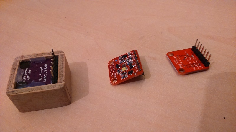
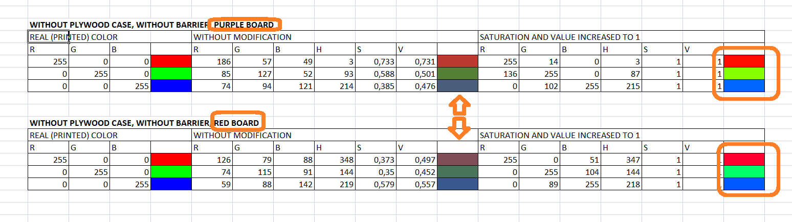
OK, my first hypothesis for the difference between boards.

Colour Temperature

Key difference between boards in my opinion is the ‘Colour Temperature’ of the supplied LED, see chart:

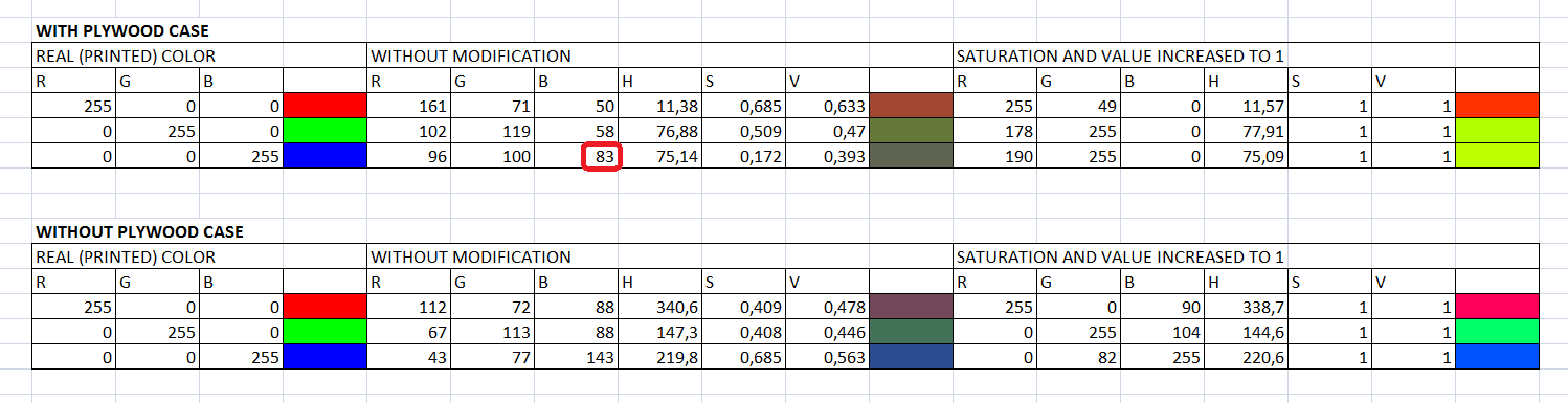
The ‘purple board’ appears to produce light closer to the Warm ~ 3000K range, whereas the ‘red board’ produces light closer to the Cool ~ 6000K range. This would explain why the ‘purple board’ has higher Red % and the ‘red board’ has higher Blue %.

To account for this could you add another variable to allow the user to select the ‘Colour Temperature’ of the LED they are using to illuminate the surface? i.e. [Warm, Cool] corresponding to the two different boards and in your driver it will adjust accordingly depending upon the light source temperature.

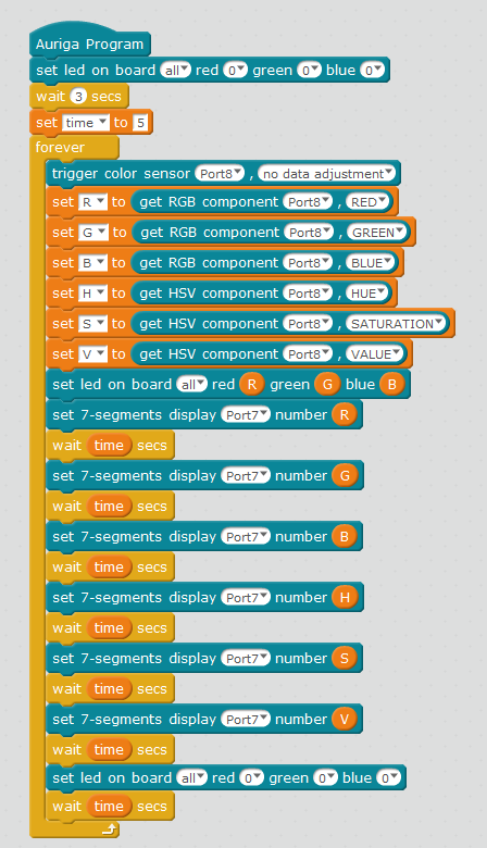
“trigger color sensor [Port6-10] colour temp. [Warm, Cool, Raw]”

Multiple Colour Sensors on TWI

(for the benefit of others following this thread)
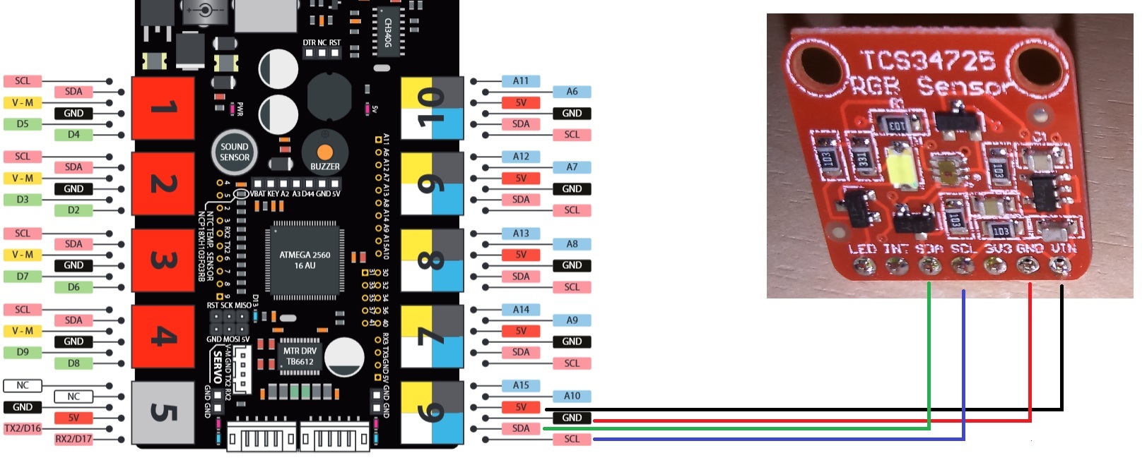
The TCS34725 has a fixed address on the I2C bus (0x29). The mBots only have a single Two Wire Interface (TWI) or I2C bus and all Ports on the mBot are attached to the same bus. This means:

  1. It doesn’t matter which Port you attach a TWI interface to, it will be on the same TWI bus;
  2. That only one TCS34725 can be addressed/used at a time, even if attached to multiple ports;

So, for your driver the Port selection is not required (in the case of using a single TCS34725).
Also only one Colour Sensor can be installed/used on the mBlock platform.

TWI Switch (Multiplexer)

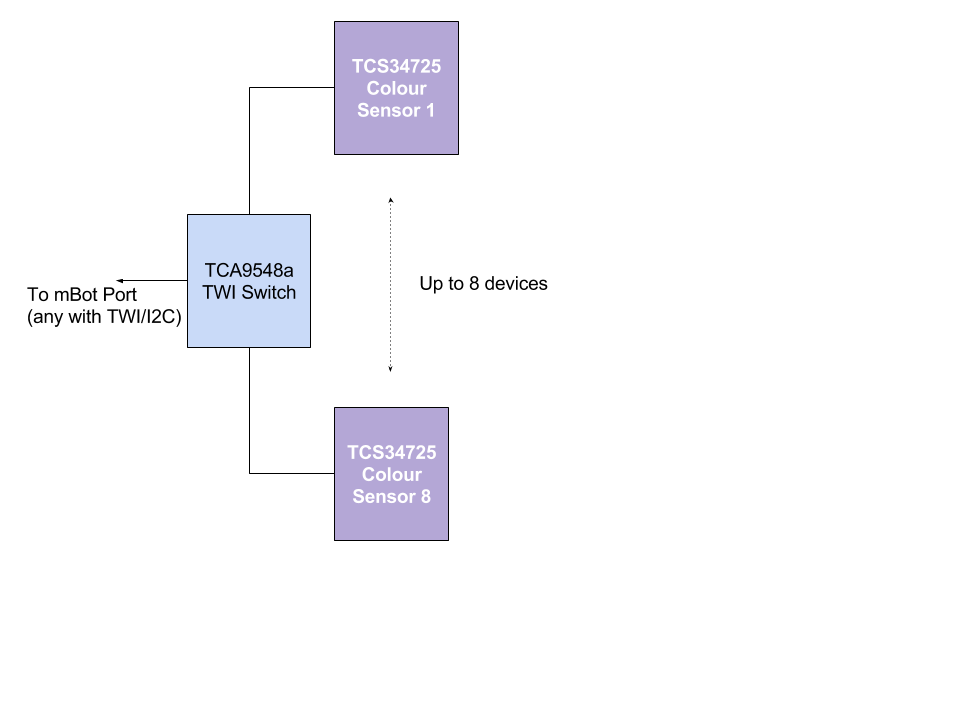
The TWI Switch (TCA9548a breakout board can be sourced for around $3 - 8USD) connects up to 8 devices to the main TWI bus. It acts as a switch so at any point in time only one of the attached devices is connected to the main TWI bus, all other devices are isolated from the TWI bus. This allows multiple devices with the same TWI address to ‘coexist’ on the same bus. A simple command is sent to the Switch to tell it which device to active, you then send commands on the TWI as normal, then switch to the next device, send commands etc.

I have just about finished an extension for mBlock that uses this switch. I will upload ASAP.

TWI Switch with multiple Colour Sensors

The TWI Switch can be used with up to 8 Colour Sensors, is readily available and would require no additional ‘custom’ parts besides hook up wires.

So the TWI Switch would be attached to a single port on the mBot, then multiple Colour Sensors (or other TWI/I2C devices) attached to the TWI Switch.


Programatically this would occur as follows:

  1. Set TWI Switch to route to the desired colour sensor
  2. Send commands to colour sensor

So for the extension, either:

  1. The colour sensor extension needs to know about the TWI Switch and include TWI Switch calls in the driver (tightly coupled); or
  2. Let the user switch the TWI Switch between colour sensors before making the call to the colour sensor commands.

The issue with the 1. is that it makes it difficult for using the same switch with multiple TWI devices. The issue with 2. is that the user will need to explicitly run any Initialisation code before using the Colour Sensor.

I like option 2 because it gives more flexibility and allows the future implementation for allowing multiple of any type of TWI devices, but happy to debate and be convinced otherwise (@tec_support -> Is there any architecture guidance around this?)

I will modify your extension to implement solution 2 and then send through for you for review/comment.

Completing the Colour Sensor and TWI Switch extension

Will need to modify both extensions to work with all of the mBot models. Can look at this once both extensions are playing together nicely :wink:


#20

Have you looked at Adafruit’s version of the TCS34725 colour sensor?
https://github.com/adafruit/Adafruit_TCS34725

I also need the value of the Clear sensors to be returned to help detect black/white/greyscale. Do you mind including this in the driver?

Here is a copy of the first version of the TWI Switch. Just need to get yourself a TCA9548a board to test.
TWI Switch.zip (3.3 KB)

I have found that the enclosure has an influence on the colour as well. Need to make sure that the enclosure in not too reflective otherwise it can reflect light back into the sensor. Something that I have used and seems to work OK is the black reticulation poly pipe. We get 13mm (1/2 inch) see photo:

I cut a small piece off and tape it to the board: