Extension for color sensor (TCS 34725)


#21

Here is an alpha version of the “Color Sensor” extension, which works with the TCA9548a multiplexer/switch.

I have also added a ‘CLEAR’ component to retrieve the value detected by the clear sensors (necessary for Black/White/Greyscale detection)

Color Sensor.zip (9.6 KB)

Screenshot of how to use it in Scratch:

Use it with a single TCA9548a connected to the mBot and then connect up to 8x TCS34725 Colour Sensors to the TCA9548a!


#22

Those are excelent ideas!

I was planing to implement multiplexor on my own, but now I see it can be found on ebay. I will immideately order one.

You are right - there is no sense using Port6-10 with color sensor which has fixed address. We can not connect two of them to mBot/Orion/Auriga board.

Concerning color temperature parameter. I saw you modified my code. I need to study that shall be done in those 3 cases RAW/WARM/COLD.

I agree with architecture aproach “2”.
You will implement general multiplexer.
I will connect several colors sensors.
Some other user will connect several sensors for some other purouse.

On last picture, “get RGBC for color sensor 0, GREEN” for LeftColour should be “get RGBC for color sensor 1, GREEN”?


#23

Good to hear Flek.

With the RAW/WARM/COOL I was suggesting this to make it easier to implement. The Adafruit library has a function that returns the detected LED temperature. Perhaps using this code to determine the temperature and then adjust the values from the sensor?

I didn’t study your colour conversion code, is this based on any colour theory? or did you work out a way to make adjust the reported colours to fit what was printed? I also didn’t look at the timing to wait for the trigger to finish, it would be good to optimise this.

I played around with using 60x gain and this worked well for my purposes, perhaps run your tests again with the higher gain (60x), now that the sensor is shielded from direct LED light (with putty) and with the low reflective ‘Black pipe’ outer shield. Would be interested to see if your results improve.

OK, let’s stay with decoupled architecture “2” and see how it goes. With the TWI Switch this means that the smallest mBot can be rigged up to do parallel colour sensing (and use this for line following), U-Sonic distance and still have 2x ports for other functions. Makes it a much more competitive bot for beginners. (If the TWI Switch is ‘piggy-backed’ onto an existing module that doesn’t use TWI/I2C then there is no loss of any ports. e.g. If using the Me RJ25 then you can connect 2 mini servos and make use of the unused TWI/I2C pins to connect to the TWI Switch, 3x modules on the one port !)

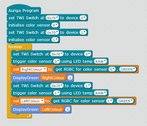
On the last picture you are right, I had a mistake and I have now updated the post with correct screenshot.

We are getting there. I have tested the TWI Switch code and seems to work as expected with the updated Colour Sensor code. I can finally get a MakeBlock robot to detect colours, absolutely needed for the robot competitions my primary students are competing in.

I look forward to seeing your updated Colour Sensor extension to see if you can improve on the accuracy of the colour detection. It will always be problematic due to the physical nature of the sensor, how people attach the sensor and how much external light from the surrounding environment pollutes the sensor. You are doing a good job and hopefully with this thread people and limit any errors in their setup, Thanks, :thumbsup: .

Connecting a Colour ( Color ) Sensor + TWI Switch ( Multiplexer ) for MakeBlock / mBot

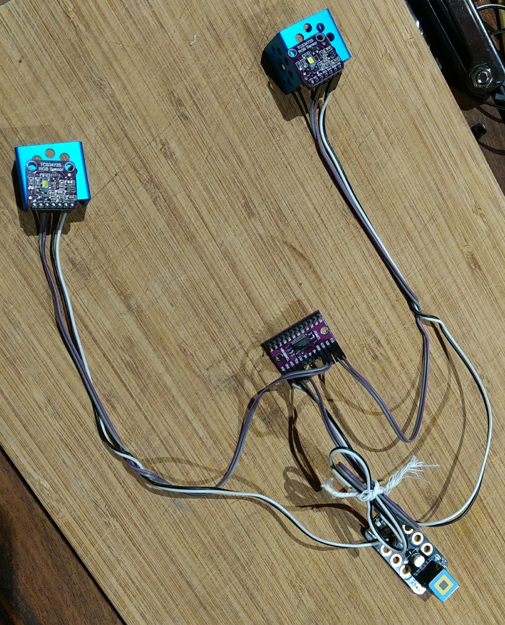
Here is one simple suggestion on how to hook up 2x Colour Sensors on the same port for anyone reading this thread:


Parts:
2x TCS34725 Colour Sensors
1x TCA9548A TWI Switch
6x Pairs of Female to Female Dupont hook up wires
1x Me RJ25 Adapter
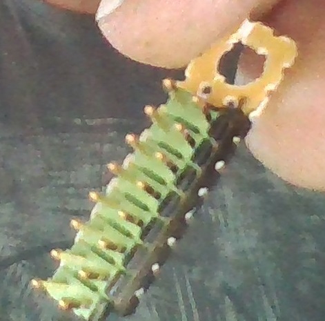
You will need to solder header pins to the Me RJ25 to get access to spare TWI/I2C, VCC & GND pins. You will also need to get VCC and GND for the two colour sensors from the Me RJ25, (or alternatively create a small power rail, take the spare VCC and GND from Me RJ25, attach to the power rail, then you have power for all your colour sensors).

Make sure you put a little bit of ‘Blue Tack’ or opaque putty between the sensor and the LED to stop the LED light directly shining on the sensor. Be careful not to put anything on the sensor!!!
Use some reticulation black poly pipe (13mm/ 0.5 inch) stuck to the board to provide a shroud to limit external light and keep both sensors close to same illumination from LED.

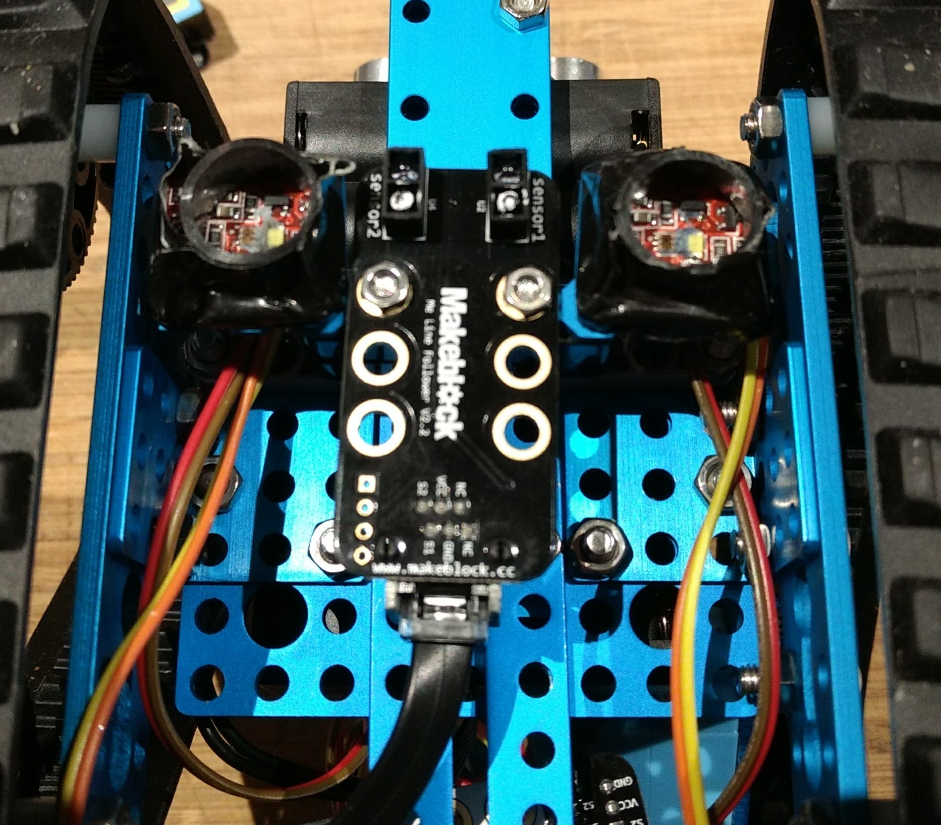
And on the robot with me line sensor between:


#24

Hi, I’m interested to try color sensor extension however cannot locate it in mBlock extensions list, has it been removed?


#25

Couldn’t find it in the extension library either. Download the Color Sensor.zip file posted by BambooClaw (June 16) then browse to it from “add extension”.
Just finished wiring it up with a single sensor myself. Tested it with the example code posted by flek_new on May 8 and looks to be working as explained. As mentioned, the LED on the sensor does seem to washout the results.

Separate note for Flek and BambooClaw… I see that you manage the LED by physical means. Have you by chance thought about (or started working on) managing it through code? found this on the ADAFruit page about this circuit.

To control the LED
(Breakout version only) - The LED pin can be pulled low to turn off the LED. This can be done in three ways:
Wire directly to ground to turn it off completely.
Wire to a spare digital pin and control it with digitalWrite().
Wire the LED pin to the INT pin and control with setInterrupt() (See Library Reference for details).

Not really familiar with the wiring on this bot yet so not sure if these could be managed with the two other unused (black/white) wires.

Also, the drop down for the sensor number for the “trigger color sensor … using LED temp…” block doesn’t seem to work (using a Mac). Looks like you can still enter in a number though.


#26

This is link to extension page:
http://www.mblock.cc/extensions/
Color sensor 1.0 can be found there.

I did not do anything on a code for a months… I plan to fix some minor features in September.
Also, I bought a multiplexer, and I will create device with 2 (or even 4) color sensors in a line. But it will take me some time…


#27

Thanks for this Flek. Looks to be some differences between the one on the extension page and the one posted earlier. Two noticed so far are there is no “clear” option on this extension page one and it looks like it starts at port6 in the drop down. For those with mBot(mCore), we don’t have ports 6-10. I have my color sensor in port 1and 2, so I imagine it would work with 3 and 4 as well. Might look into your multiplexer design, but for now the project I’m working on just needs the one.

Is this extension one “official”? If so, I might look into how hard it would be to add the other ports and the digitalWrite(), but I haven’t touched C++ in years so there will be a bit of a learning curve with this…


#28

Yes. there are two versions of color sensor driver.

I creted one which is on Makeblock extension page. Let’s call it “official”.
BambooClaw modified that version according his needs (and you can fin that version in this thread, posted by BamboodClaw on 17th of June). He needed “clear” component, and he fixed some port issues (if I remember correct).

Originaly, I implemented color sensor driver for Auriga. But I think it might work on mBot, because port number is not checked anywhere, and it uses I2C protocol for communication.

I will fix that issues, and commit them to Makeblock extension page somewhere in September…


#29