The User Guide and Troubleshooting of Stepper Motor and Stepper Motor Driver


#1

Here is a user guide of How to run the stepper motor by Me 2H Microstep Driver. You can learn it in 5 minutes.

For the code and library, you can find them here,

Library,AccelStepper_library.zip (12.5 KB)
Code, http://wiki.makeblock.cc/index.php/Me_2H_Microstep_Driver#Sample_Program

The troubleshooting

You can see the complete document here,

http://www.makeblock.cc/makeblock-2h-microstep-driver-user-guide/

Or, http://wiki.makeblock.cc/index.php/Me_2H_Microstep_Driver

p.s. The working voltage of the stepper motor on our website is 12V


#2

Great Tutorial !!

I think that u must provide more info about voltage, in this tutorial and in the driver it said that you must apply 12-36 VDC
The old specs of the motor: http://www.makeblock.cc/42byg-stepper-motor/ said something like 5 V but now it said 12 V

Now if I look for a datasheet on internet i got 3.4 V

http://store.kysanelectronics.com/servlet/-strse-70037/42BYGHW609/Detail

Maybe you can provide more info or warnings about max voltage, etc

Thanks !!!


#3

@Markuitos, that’s very kind of you get so much datasheet here.

However, for the voltage, I think the motor on our website is 12V rather than 5V.

And I think different kind of factory has different kind of specifications. “42” just means the length of stepper motor. The voltage is different between the motors.


#4

@Johnny a time ago I see a 2.55V in the first makeblock datasheet that was posted on blog:

http://blog.makeblock.cc/wp-content/uploads/2012/11/42BYGHW609D4P1-Datasheet.pdf

In fact all the internet datasheets of the model: 42BYGHW609 said 3.4V I just want to know if that model can handle 12V without problems and maybe you can be more specific in Video and in the Wiki about the voltage limits

Thanks !!


#5

I have to admit that it’s a little confusing. I will check that and make a specification in Video and Wiki. Thanks for your remind!!!


#6

@Johnny of course I just post it to clarify to other users so is no doubt about what voltage to use :slight_smile: just my 2 cents

Have a good day, cheers


#7

Hi @Johnny, thanks for the video! You guys are always responding quickly to questions and requests, and I’m very grateful for you commitment to your customers!
I was wondering: in the video, it shows the wires connected as:
A+ Green
A- Black
B+ Blue
B- Red

However, in your instructable for the XY-Plotter, it has it as:
A+ Red
A- Blue
B+ Black
B- Green

In the driver user guide, it has it as:
A+ Black
A- Green
B+ Red
B- Blue

What difference does this order make? Does it change the motor’s direction? Is there a chance of damaging the motor if it is wired the wrong way?


#8

Hi @sammccants,

  1. Our stepper motor has two phase. So it doesn’t matter you change the connection order between phase A and phase B. Which I mean Black and Green could be connected to A orB, Red and Blue could be connected to B or A. And yes, it would change the motor direction.

2, And,
A+:Black A+:Green
A-:Green or A-: Black Both of the connection type are OK.

3, There is only one rule you need to follow, which is you can’t mix them together.

For example, this kind of connection type is wrong, it would make damage to the motor.

A+:Red
A-: Black
B+:Blue
B-:Green


#9

Sounds good! Thank you, as always, for being incredibly helpful and responding quickly! Keep up the great work!


#10

I purchased XY plotter from Makeblock recently. I assembled it, but it doesn’t work. Then I found that I have to upload a software. I tried few times but couldn’t connect the computer to the plotter to upload the arduino software. Could you please help me a guide me step by step with the software. Very grateful


#11

Hello,

sorry I am a beginner with no electricity background. Here are a couple of questions:

This sample program:

* File Name          : Me_AccelStepper.ino
* Author             : Ander
* Updated            : Ander
* Version            : V0.0.3
* Date               : 12/11/2013

makes one stepper motor move, even if I have two stepper motors connected (same connections as in the xy-plotter).
What part of the program should I change to move the other motor ?
Is it this line ??

AccelStepper stepper(AccelStepper::DRIVER, 13, 12); // 13-PUL,12-DIR

Second question:
This line in the code controls the speed of the motor:

stepper.setMaxSpeed(200);

(Note the 4000 in the sample program is dangerously fast…)
Changing this value changes the speed of the motor, but can I also use the dip switches for this ? Is it save to change the SW5 SW6 SW7 while the motor is running ?
Or do you need to set these switches before uploading ?

cheers,
paul


#12

Hi @paulcobbaut

As for the 1st question, you are right. You can try to write another code to define more stepper motors

In this case, the stepper motor is connected to Port_3. You can see that on the PCB, the Port_3 is corresponding to D12 and D13 (the pins on Meduino). So it is

AccelStepper stepper(AccelStepper::DRIVER, 13, 12); // 13-PUL,12-DIR

The Port_4 is D8 and D2. The Port_6 is A2 and A3. You can try to modify the code by yourself.

Regarding the 2nd question. You are right, the SW5-7 are used to modify the micro value of the stepper and it would change the rotate speed. If the value is 8, the motor would move 2008=1600 steps in a round. If the value is 128, the motor would move 200128=25600 in a round. It would be very slow.

Don’t change the DIP switches when the power is on. It would break the driver box.


#13

Hello,

When in your specs you say “the motor would move x steps in a round” what do you mean with a round? a full revolution?

And how do I relate this to the setMaxSpeed() command? For example, I have a motor that has 200 steps/revolution. I understand that if I inpunt setMaxSpeed(200) then the motor will move at 1 revolution per second. How does the micro setting affects this parameter?

Thank you


#14

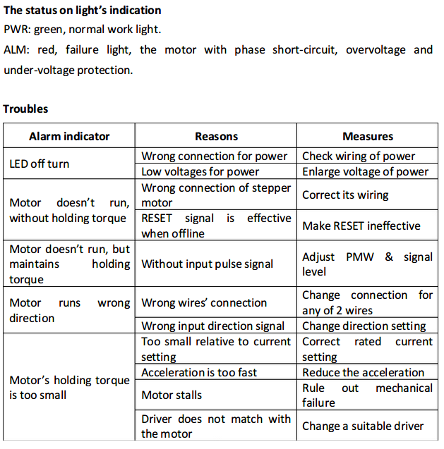
I am confused about the DIP switch settings for the XY Plotter 2.02. They are On On Off, which from the data sheet means the microstepping rate is 16x , ASSUMING the little stepper controller is the same as the large controller to which the datasheet refers, and switches 1 - 3 equate to switches 5 - 7.

When I try to work out the microstepping based on the figure of 174,9781 ppm given in the Setting.ini file used by GRemote, this is what I get, a suggestion that the rate is 32x, double what the document says it should be.

18-tooth pulley
Belt pitch 2.032 mm (from spec, confirmed by vernier caliper along 18 teeth )
distance moved in 1 revolution = 36.576 mm ( 18 * 2.032)
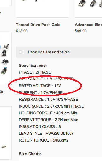
Stepper motor 1.8 degrees = 200 steps per revolution
single step = 0.18288 mm ( 36.576 / 200)
1mm = 5.468066 steps at 1x stepping rate ( 1 / 0.18288 )

Setting.ini X pulses per mm = 174.9781
Apparent stepping rate = 32 ( 174.9781 / 5.468066 = 31.9999 )

Switch settings of on on off are for 16x, pulses/rev = 3200
distance per pulse = 36.576 / 3200 = 0.01143
pulses per mm = 1 / 0.01143 = 87.48906

The setting,ini value 174.9781 / 87.48906 = 2

So everything seems to be telling me that the switch settings shown in the photos for the XYPlotter 2 assembly are for 32x, unless I am misunderstanding something here.


XY Plotter v2 understanding X_STEPS_PER_MM and $6 command
#15

hi i am new to this motor stuff…do i need a diver to work the Stepper Motor 42BYGHW609


#16

Hi Johnny and others,

Thanks for the great user guide, it really helped a lot!

The motor is functioning as expected, but I’m wondering if it is normal that the motor is getting extremely hot? Even when the motor is idle (but connected to the 2H and the 2H to the Arduino).

Is this normal and are there other experiencing these hot temperatures?

I’ve setup the motor with the same wiring as the video:
A+ Green
A- Black
B+ Blue
B- Red

SW1: off
SW2: off
SW3: off
SW4: off
SW5: on
SW6: on
SW7: on

This is the Arduino test sketch I’m using:
#include “MeOrion.h”
#include <SoftwareSerial.h>
#include <Wire.h>
#include <AccelStepper.h>

int dirPin = 12;// WIT the direction pin connect to Base Board PORT1 SLOT1
int stpPin = 13;// GEEL the Step or Pul pin connect to Base Board PORT1 SLOT2
AccelStepper stepper(AccelStepper::DRIVER, stpPin, dirPin);


void setup()
{
    Serial.begin(9600);
    stepper.setMaxSpeed(1500);
    stepper.setAcceleration(10000);
}

void loop()
{
 
  if(Serial.available())
  {
      char a = Serial.read();
      switch(a)
      {
      case '0':
          Serial.println("Move to 0");
          stepper.moveTo(0);
          break;
      case '1':
          Serial.println("Move to 20000");
          stepper.moveTo(20000);
          break;
      case '2':
          Serial.println("Move 50");
          stepper.move(50);
          break;
      case '3':
          Serial.println("Move 100");
          stepper.move(100);
          break;
      case '4':
          Serial.println("Move 200");
          stepper.move(200);
          break;
      }
  }
  stepper.run();
}

#17

Hello,

I am using two Microstep Driver MA860H. One of the driver has red light (Alarm) ON and the other one has green light ON. Both of the Microstepping Driver units run from the same power converter.
But now only one of the driver is showing red light. Can you please suggest me what should be done to remove this fault (Alarm - Red light) ?
It will be a great help.

Thank You in advance.


#18