Music Robot


#1

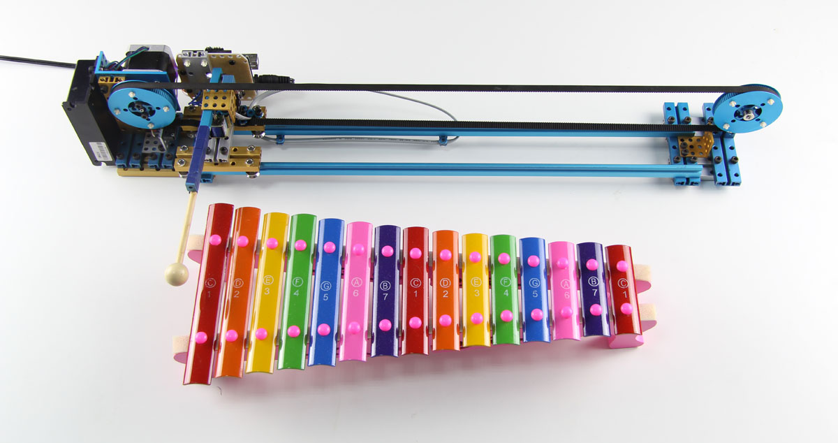
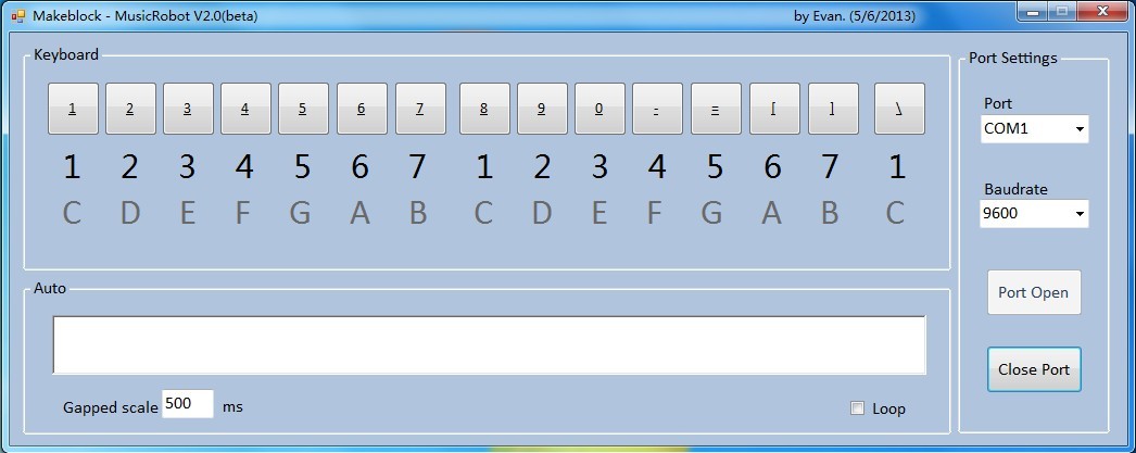
This is music robot controlled by application via USB cable installed on computer, and it can be controlled by the SmartPhone through the bluetooth.

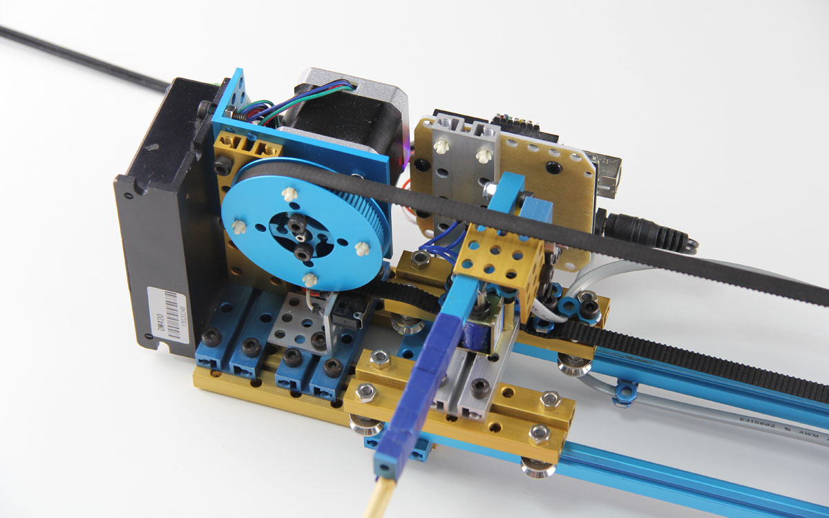
The music robot was built with the timing belt, sliding rail, step motor, electromagnet, motor driver and an Arduino Uno. And even you can build a play the piano robot with Makeblock by yourself.
The special application for Android Phone is in planning.


#2

We will make a step by step guide about how to build this music robot on instructbles soon.

Eric from Makeblock.


#3

Cool, It’s better to put a part list here. and hope you will provide the source code. that will helps a lot.


#4

If it can make me well the rhythm of the music will be much better…


#5

The step by step guide of how to make this Music Robot has been uploaded on instructables. You can see it here:


#6

The software on the upper-computer(such as Mac or PC) would be better if you use open source tools to develop, C# is base on .net framework which can be use only on Windows platform. And Visual Studio is a huge copyright software, not so easy for users to change or redevelop your programme.
I recommand processing or Flash ActionScript etc… if your programme just aim to print some String to Serial Port to tell Arduino something, they also have more elegant GUI and OS Platform Independence…


#7

where is the source code for this? I have look at the instructable article and it points to teh download section here, but I do not see it listed??


#8

Hi billtylerjr,
You can find the source code here :http://makeblock.cc/download/
Or you can click http://blog.makeblock.cc/wp-content/uploads/2012/11/MusicRobot-V2.0.zip to download the code.


#9

I don’t find it under the two mentioned links - the first one links to a page with some instructions, but no download for software except the github repository (which doesn’t include MusicRobot, just the library). The second link is dead …

I guess, the software for Music Robot got relocated somewhere…?


#10

this link : http://blog.makeblock.cc/wp-content/uploads/2012/11/MusicRobot-V2.0.zip
:smile:


#11

What version of the AccelStepper Library did you guys use for this project the one I have does not work with it, as it gives me an error on the constructor.

AccelStepper stepper(AccelStepper::dRIVER, 12, 13);; // 12-PUL, 13-DIR

Thanks,
Harold

.


#12

I think you can do:

AccelStepper stepper(1,12,13);

params: 1 = driver mode
12, 13 = pins for PUL, DIR

for me this works … (AccelStepper v1.37)


#13

Yeah that is what I did and it is working.


#14

Hello,
it appears that I have a newer version of this kit. It contains RJ11 cables but no information on how to connect the electronics. From the wiki pages and the code I assume that I have to connect the limit-switch with Port-4, the Microstep driver with Port3 and the solenoid to one of the motor ports (orange). However, that does not reflect the example code using D9 and D10 for the magnet. On top, there is a third RJ11 cable that seems to have no function which is weird.
Can you please update the documentation and code to the new kit version using the Me-Shield?
Kind Regards, Mathias


#15

Got the same version for the kit. I think all of the above is correct:

  • Me-Base Shield provided instead of the “loose” electronics modules in the instructable (good, but the documentation needs updating, it’s fairly confusing at first)
  • extra RJ11 cable with no known function - lack of up-to-date documentation doesn’t make it any easier!
  • limit switch has an RJ11 socket instead of wires, and the instructions how to mount it are out of date
  • solenoid mounting is different to what’s described in the instructable
  • different beam types (or at least: fewer 80-type beams than are required by the instructable)
  • the makeblock.cc/download doesn’t contain the software for Music Robot

MathiasW: With built-in software, port 3 for limit switch and port 4 for stepper driver seems to work - sending an ASCII character of code 0…16 seems to actually move the stepper and trigger the solenoid. The solenoid needs to be connected to the orange side port next to port 5 (as in. the one with the white circle on it).