Hi @satyajit,
I have replied you in the original topic.
Hi, I want to use the Android app. I followed all steps, all cables are connected. The one motor move when I turn the thing on or when I uploaded the code to the meduino. It also connects via the bluetooth. I select an image and click start but nothing happens it draws on the phone and that’s it. Is there a way of sending a custom drawing directly to the arduino? what is the problem?
////EDIT////
I tested the solenoid with the DC motor example program, I tested the steppers with the stepper sample programs, I tested the limit switches with the sample program, I tested the bluetooth with the sample program, all are working fine. But when I upload the plotter program one motor moves a bit then nothing happens, it connects to the app via bluetooth and the app draws something but the plotter does nothing. Could it be a communication problem?
Hi, @kilologin
Could you take some pictures of the XY to show the connections?(especially the baseshiled and the limit switches).
Here it is. It seems that the connections are all ok, I tried combining the test codes Me_AccelStepper.ino and TestLimitSwitch.ino in one, and it seems that the problem is there, as soon as they are combined the steppers stop moving and only the code for the swithches works.
It seems that you have the right connections. I just want to make sure you have plug the power cable to Baseshield, not Meduino(Since you have tested the steppers alone and it could work, the connection should be right)
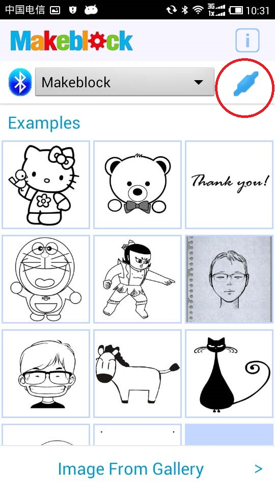
Could you check you have got the “connected” mark on the right-top corner of the App? Just like this:
Yes I got the connected mark. During the initializing sequence if the steppers are stopped by the switches then when trying to draw the pen up and down works in sync with the app, but the steppers do not move. I discovered, that if I add any additional information on the stepper loop on my test program, the instructions for stepper won’t run. That may be not the issue with the XY plotter but that is what I can do to test, I think it has something to do with the serial write… for example in the following code, if I uncomment the // limitswitch(); the steppers won’t move but I will get info from switches displayed in serial port, and if I comment it, the steppers move accordingly (maybe something to do with the serial print?)
#include <Makeblock.h>
#include <Arduino.h>
#include <SoftwareSerial.h>
#include <Wire.h>
#include <AccelStepper.h>

// Define a stepper and the pins it will use
AccelStepper stepper(AccelStepper::DRIVER, 13, 12); // 13-PUL,12-DIR

AccelStepper stepperY(AccelStepper::DRIVER, 2, 8); // 2-PUL,8-DIR

MeLimitSwitch limitSwitch(PORT_8); //Me_LimitSwitch module can only be connected to PORT_3, PORT_4, PORT_5, PORT_6 of base shield or from PORT_3 to PORT_8 of baseboard.
MeLimitSwitch limitSwitch2(PORT_7); //Me_LimitSwitch module can only be connected to PORT_3, PORT_4, PORT_5, PORT_6 of base shield or from PORT_3 to PORT_8 of baseboard.
// Define a stepper and the pins it will use

void setup()
{
  stepper.setAcceleration(80000);
  stepper.setCurrentPosition(0);
  stepper.setMaxSpeed(4000);

  stepperY.setAcceleration(80000);
  stepperY.setCurrentPosition(0);
  stepperY.setMaxSpeed(4000);
      Serial.begin(9600);
    Serial.println("Serial Stablished!");
}
long current_position;
long current_positionY;

void loop()
{
  current_position = stepper.currentPosition();
  if(current_position>=8000){
    stepper.moveTo(0);
  }
  if(current_position<=0){
    stepper.moveTo(8000);
  }
  stepper.run();
  current_positionY = stepperY.currentPosition();
  if(current_positionY>=8000){
    stepperY.moveTo(0);
  }
  if(current_positionY<=0){
    stepperY.moveTo(8000);
  }
  stepperY.run();
 // limitswitch();
}


void limitswitch()
{
   if(limitSwitch.touched()) //If the limit switch is up, the "readUpPin" return value is true.
   {
     Serial.println("State: UP.");
     delay(1);
     while(limitSwitch.touched()); //Repeat check the switch state, until released.
     delay(2);
   }
   if(!limitSwitch.touched()){
     Serial.println("State: DOWN.");
     delay(1);
     while(!limitSwitch.touched());
     delay(2);
   }
   if(limitSwitch2.touched()) //If the limit switch is up, the "readUpPin" return value is true.
   {
     Serial.println("State: UP2.");
     delay(1);
     while(limitSwitch2.touched()); //Repeat check the switch state, until released.
     delay(2);
   }
   if(!limitSwitch2.touched()){
     Serial.println("State: DOWN2.");
     delay(1);
     while(!limitSwitch2.touched());
     delay(2);
   }
 }
UPDATE:
I noticed that the speed on the steppers was different, in the instructables there it is suggested to have SW2 ON only, somewhere else to also have SW7 ON, now it moves together with the pen (they may have been moving but couldn’t see due to super slow speed, by the way the linear motion slide units are shit and stick I had to use lots of D40 and still not very smooth, but that is another story). Moral of the story, be sure SW7 is ON as SW2. I will conect the pen and see how the drawing looks, I hope I did not mess up the resolution etc. I still don’t know why my test program doesnt work but I am happy the printer moved. Thanks a lot.
///EDIT///
Yes the slide units sticking is a big issue for drawing, the area of the drawing is also very small… not even a quarter of the whole area.
When trying to troubleshoot the XY Plotter, this guide comes up as the name suggests it is a general guide for the XY Plotter and how to troubleshoot it. I hope this thread can develop into the subject that it used. I bought the XY Plotter a while back and have yet to get it working. I didn’t have a lot of expectations about it, so I am not really disappointed. My issue is that I have yet to get my phone to send anything that is picked up by the motors that results any kind of any image. I have verified the stepper motors work, the drivers work, the bluetooth module and the arduino works. I notified makeblock that the baseshield had to be the issue, but still do not have the replacement that they said was being sent (I received the ver. 2 of the baseshield with the XY Plotter kit but they decided on sending me version 1, hopefully if I get it that will not be an issue). I don’t see getting this working as a big milestone as the drawing area is much smaller than the size of the plotter that could be used.
It seems like this is a nice project mechanically, the sample program for the phone along with the code that it uses does not seem to be a good starting point for those who want to take this project and do something novel with their own ideas. My conclusion overall is that it was worth the build, but I think one is better off finding an alternative gcode interpreter to drive this device. Doing that will allow you to control how large the drawing area will be, improve the use of customizing the hardware to your own needs and have an established set of hardware around the XY Plotter.
@Johnny please centralize all of the troubleshooting information into one thread, it seems like it is spread across many areas.
Hi @todd, thanks very much for your suggestion about our products. Could you send your address to me by the private message again? I’m sorry about the Baseshield but I didn’t get it in the support@makeblock.cc
Hey @Johnny, is there a way to test the baseshield easily? It’s the only part of the hardware that I am having trouble with, I did email you my information so a new one can be sent. However, I like to be able to test parts independently. If you have a way to test this baseshield, please reply with the idea you have.
I get the email and Alice will send a new Baseshield to you ASAP. Could you try the Gcode to control the XY Plotter? It will help you test every part in the XY Plotter.
I followed the steps, but still have not had any response from the baseshield. Could you let me know the wiring from the baseshield to the driver for the XY Plotter @Johnny? I see it uses an RJ11 connection and has three wires: red, white, black. I notice the driver has 4 inputs and the enable does not seem to be used. Is that correct? Please let me know the wiring so I can confirm if it is correct.
If I could @Johnny, I have one more question for you. In the code, there is a line that writes:
AccelStepper stepper(AccelStepper::DRIVER, 2, 8);
I know that the 2 is for the PUL and the 8 is for the DIR. But how is the port selected in that statement? I see the comments show it is PORT 4. However, is the DRIVER a variable that is storing the value 4? How are the different ports referenced?
@Johnny We’re trying to add more flexibility to the way XY Plotter works by adding a few little modules but we’re being limited by how the base-shield interacts with the Arduino itself. Could you explain the construction a bit and why have telephone cables been used as connectors?
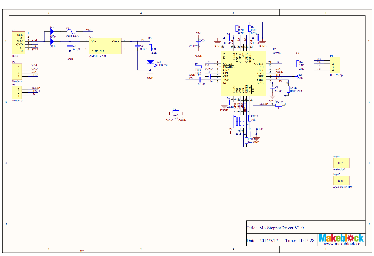
We also want to know how the Micro-step driver is actually constructed on the inside (PCB) level/diagram as that would better help us using the Gcode methods.
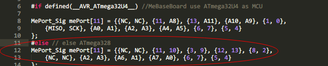
Hi AsadMoeen, You could get the schematic of Me stepper motor driver here
And you can find the Baseshield Port->Pin information on PCB, or in Makeblock.cpp.
Where can I get the schematic and components list of the 2H-microstep driver?
I need all the ICs its using including the schematic.
Hi,
I use GRemote to send GCode directly to the xy plotter, it works very well. I would like to know if it’s possible, in terms of a value read, that a program send automatically to the plotter the appropriate GCode.
For example, if the program reads 1, he knows that he has to send the Gcode A.
If it reads 2, he knows that he has to send the Gcode B etc
How can I do this using GRemote ?
Thanks 