Problems with Gyro-Module of the Electronic-Kit for Scratch&Arduino


#1

Hello,

I’m using the Gyro-Module with ScratchBot to read the X, Y and Z angles.
Everything works fine for X and Y and I receive values between -90 and +90
depending on the position of the module.

But when I try to read the Z-Axis with the “3-axis gyro Z-Axis angle” Scratch-Block,
the return-values seems to reflect the acceleration of the module.

What did I do wrong?

Regards

Erik


#2

Hi Erik,

Thanks for your post.
Z-Axis value is not angles, please ignore the value, I will reply you via email, thank you.

Makeblock Community Team


#3

Hi,

ok. Thanks for your support!

Erik


#4

Hi Erik,

Can you share the support you had because, the same as you, I don’t understand what represents the Z-Axis?

Thanks

Manolo


#5

Can you provide the info on the outputs to the community? I’v been playing with the gyro and am also seeing weird numbers. I would have thought I should see 360 deg of info on each axis but that doesn’t seem to be the case.


#6

Hi,

With mblock,
I’ve succeeded to uses the angles values (X and Y but Z, I still dont know how to use it, can you give me any information about that?)
The module is also supposed to deliver accelerration but from mblock, no function is available for that!
Why?
Do you know anything about that? Is it coming soon?

Thanks for your answer


#7

Hi all,

as the use of the MeGyro module is badly explained by the makeblock team, I will try to explain a few aspects of using a gyro and give some hints on how to start exploring it. To follow this post you need to use the Arduino API, not Scratch.

What is a Gyroscope
A gyro is an attitude indicator. It provides indication of yaw, pitch and roll of a vehicle. These are relative measurements, comparing the current orientation with the orientation at time of calibration of the gyro. The gyro can not be used to measure the absolute geographic orientation, like a magnetic compass. But the absolute orientation can be calculated, when the absolute orientation in space during calibration is known (not taking into account the drift here, for simplicity).

The makeblock MeGyro module also contains an accelerometer and a compass. When looking at src/MeGyro.cpp, one sees the accelerometer parametres (accX, accY and accZ), but no function is provided to retrieve them. As this is just C code, one could add the functions to the library, similar to the getAngleX/Y/Z() functions. The same would apply to the compass functions. Most likely this would also require some studying of appropriate filtering and drift-compensation mechanisms, in order to provide sensible values. Study the math used to achieve the angle-values, in order to get an idea…google and wikipedia are also your close friends here. E.g. with the accelerometer functions at hand, travelled distances could be calculated.

How to Apply the MeGyro Module in Practice
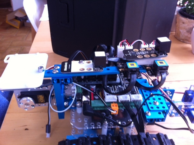
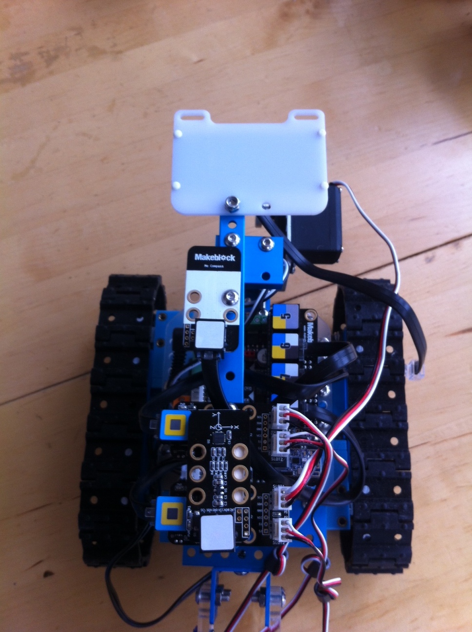
When looking at the gyro module a small drawing is visible, indicating the coordinate system. All the gyro does is measuring rotation angles along these three axes. It is important to mount the gyro so that the axes point to the right directions, in order to match the familiar right-handed coordinate systems.

The X-axis should represent the length axis of the vehicle. It will then indicate the “roll” attitude.
The Y-axis points through the sides of the vehicle. The returned values for Y represent the “pitch” attitude.
The Z-axis is the vertical axis, pointing through the vehicle. It provides the “yaw” attitude. The Z-Axis can point upwards or downwards, which will result in either positive or negative values for “right” and “left” deviation.

The values returned by gyro.getAngleX/Y/Z, after gyro.update() are given in +/- degrees deviation from what has been measured/calculated at gyro.begin(), when X, Y, and Z are set to “0”. So, if Z = 3.0, it means that the vehicle has turned 3 degrees to the right (I prefer right to be positive), since the last calibration of the gyro.

The MeGyro Example Sketch
This sketch should be used to find out about the correct function and orientation of the module. It is important to use Makeblock Library V 3.X for this, as earlier libraries are buggy for the gyro. Just load and run the sketch and move the module, simulating pitch, yaw and roll. Observe the measurements, returned for the three angles by watching the output of the sketch in serial monitor. Once you know how to mount the module on your vehicle you are ready to go. For a start, you could write a sketch to let the module drive straight forward, self-correcting for deviations of the heading.

Hope this little explanation helps for a starter.

Cheers, Stefan


#8

I too would love to know what the z values are please. The X Y make sense and stay fairly locked, but the z values don’t and continuously drift in one direction.

Help please.


#9

Hi Profx,

We use the MPU-6050 chip for the Me 3-Axis Accelerometer and Gyro Sensor.
According to the working principle of the MPU-6050, the Z value will drift in one direction.You may search for the datasheet of MPU-6050 online have a check. Actually, there are a lot of 3-Axis Accelerometer and Gyro Sensor from other manufacturers perfom the same way. For some 3-Axis Accelerometer and Gyro Sensor which has its Z values locked, normally has added another chip which has calibrated this parameter.


My mBot Ranger gyro-Z value keep increasing
#10

I will have a look for the datasheet, but it might be beyond my level of understanding. The speed of the drift is high, about a degree a second.

All I am trying to do is to get my bot to be able to turn in moderately precise increments by sensing its position as it moves (rotates in z-axis). I thought the gyro might simply solve that, but it seems not the case.

I’m also struggling with the Me Compass. In both cases I ideally would like to use Scratch rather than Arduino as I’m developing a project for kids.

Any advice gratefully received. Thanks in advance


#11

I did have a read of the data sheet, but it was largely way above my level of electrical engineering.

It did mention that you could add a magnetic compass to improve the accuracy, but I’m guessing there is no easy way to use the Me Compass for this?


#12

Hi @ProfX

To my experience, 1º/sec is way too much of a drift. I use the gyro to keep my bot running straight for larger distances and it works absolutely fine. If you want to program a turn, you take a reading of the z and turn until your heading equals that reading plus the turn angle you want. Dead simple.
You should probably record your z value readings together with a timestring, for some larger periods and post the drift rate to @tec_support. May be, your gyro is malfunctioning. But please make sure you have it mounted correctly and the installation does not move at all for the test.

Cheers, Stefan


My mBot Ranger gyro-Z value keep increasing
#13

Thanks @srothe, I’m going to give it another crack over the next couple of days and will let you know how I get on.
Always possibility of ‘operator error’ (brain fade) so to speak, so I’ll check I’m not doing anything ultra dumb.
I’ll also look at a timestring as you suggest.

What seemed to be happening is the at the x and y just wobbled with a small ± 0.1 and essentially stayed locked, but the z axis ticked away like a clock.

I was indeed hoping it was going to be super simple as you describe. Just read value and go for a target offset.

A slow drift of even a degree or two a minute would not be disaster, but this is quite a lot more rapid than that.

Any pointers at useful documentation for either the Gyro or the compass would also be massively appreciated, but maybe nothing quite as technical as that datasheet. Thanks again, Nick


#14

Ah ha! Might have found a culprit or at least an accessory to the fact.

I disconnected the Me Compass and the drift reduced I would say 20 fold. Apologies if this sounds like nonsense, I’ve tried it with and without 3 times and am just calling what I see.

Gyro z-axis still drifts a bit (more than the x and y), but in a much slower way that I think will be manageable during most turns.

Going to return to the original plan, thanks again for your help (I might well need more!).

Cheers, Nick


#15

Could you upload a picture of your program if it’s in scratch? I’ve been struggling to figure out how to program my gyro sensor in Mblock.


#16

Now, that’s an interesting one. Could you post an image showing your setup, with both, the gyro and the compass mounted? Should be interesting to hear a comment from @tec_support regarding mounting instructions.


#17

Hi Bill, afraid my code will be very disappointing as at that stage I was just trying to get my head round how the compass and gyro worked.
Initially I was just using the Show Face command in a forever loop to display the Z-axis angle of the gyro on the basic LED screen, and I was rotating the bot around by hand to see what happened.

I am yet to come up with an elegant solution to the axes jumping between -180 and +180 that I am happy with, and to be honest, was going to do a bit more research rather than banging my head against it.

In fact, I suspect @srothe would be a much better person to ask than me (I was plucking up courage to ask to see his work, as it happens).

Instead, once I discovered how to calibrate the compass, I switched to that as it gave me a bigger range to play with before I have to address the issue of the leap from 360 to 0. All I am doing at this stage is experimenting with how best to get the bot to do consistent relatively precise 45 or 90 degree turns, and trying out different motors (encoders unsurprisingly seem much better than the standard DC ones), as well as playing with different grippers and servos for a claw.

I’ll try to take a screen grab of that code if you like and can post it, although it is very basic.

I’ve also just received an Auriga board, so was going to rebuild the bot with that and see how its gyro fares. Not enough hours in the day though.


#18

Hi Stefan,
Since the earlier post, I’ve taken off the gyro and put on two servo controllers instead. To give you an idea of how it was laid out, I’ve just balanced the gyro on top of them for these photos.

If you imagine the gyro was mounted on that long thin plate/beam (with some plastic spacers to stop it actually touching), in the same orientation as the compass,and obviously the two controllers weren’t there.

So effectively both the gyro and the compass were mounted on the same long strut.


#19

Hi @Bill_W , here is my rough code for testing the compass. It only works though if you have a start orientation for the bot that steers clear of crossing from 360 to 0, so not terribly useful as yet.

I was mainly trying to see if I could get some precision despite the Bluetooth lag, whilst using Scratch and running the code from the laptop and not uploading it to the bot.

Slow moving encoder motors seem to help, although you’ll notice that I actually only ask it to turn 85 degrees, even though I’m aiming for (and largely getting) a 90 degree turn.

I imagine the gyro could work in much the same way reading the z-axis, but am yet to put it through its paces, and that has twice the flipping axis problem than the compass has, so needs a bit of thought. Might need some help myself with that bit.


#20

BTW, I’m actually finding that the driving forward in a straight line is less accurate than my turns now!

The endless Show Face commands are just so I can keep an eye on what the bot is trying to do